
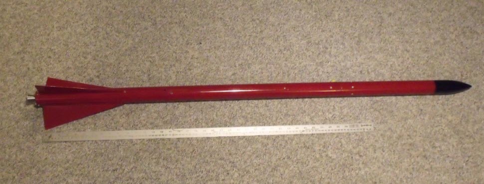
3D printed nosecone for Xi rocket

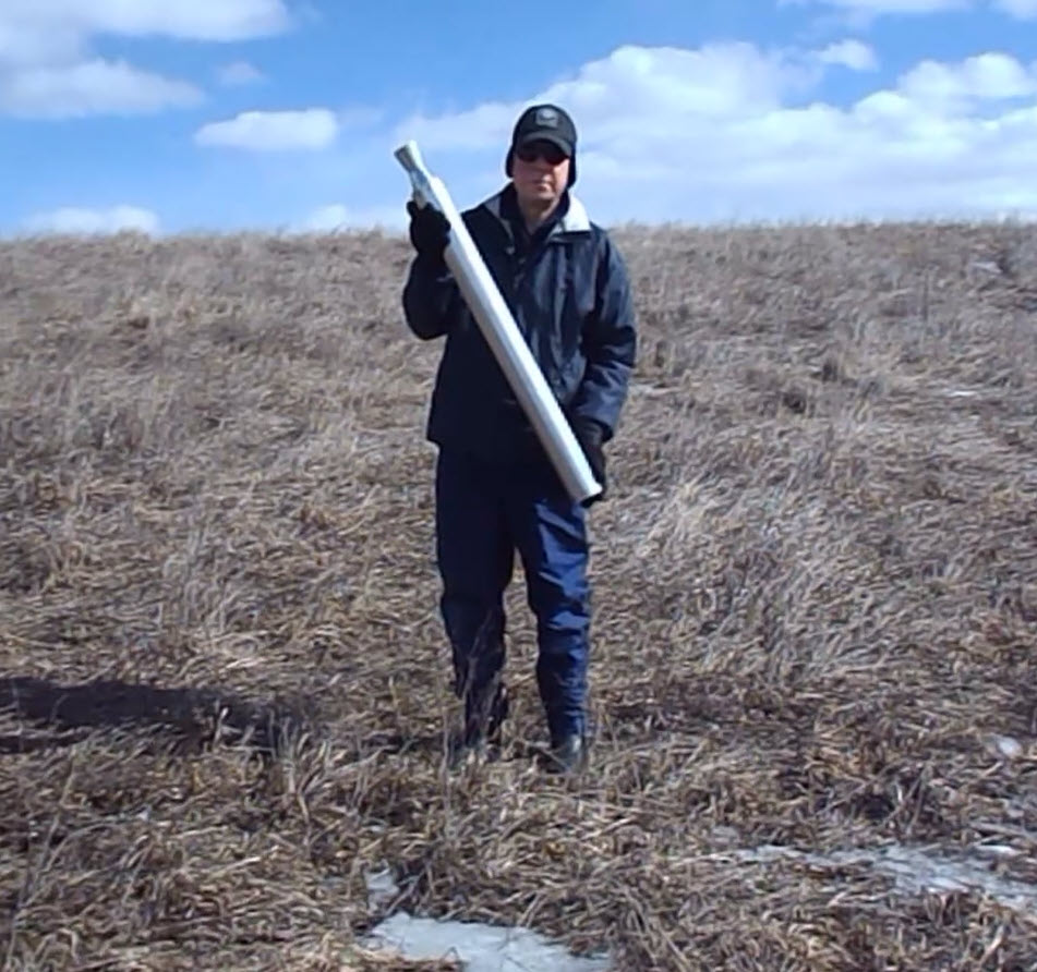
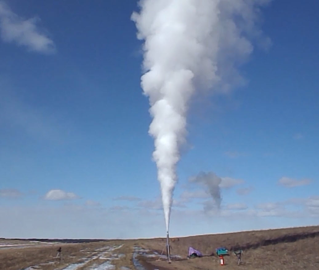
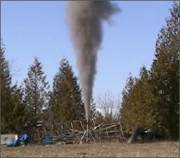
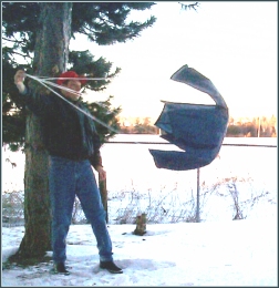
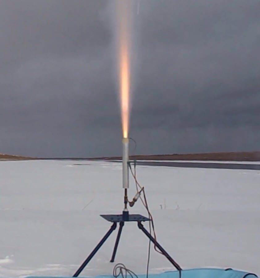
NTM-5 nozzleless rocket motor firing

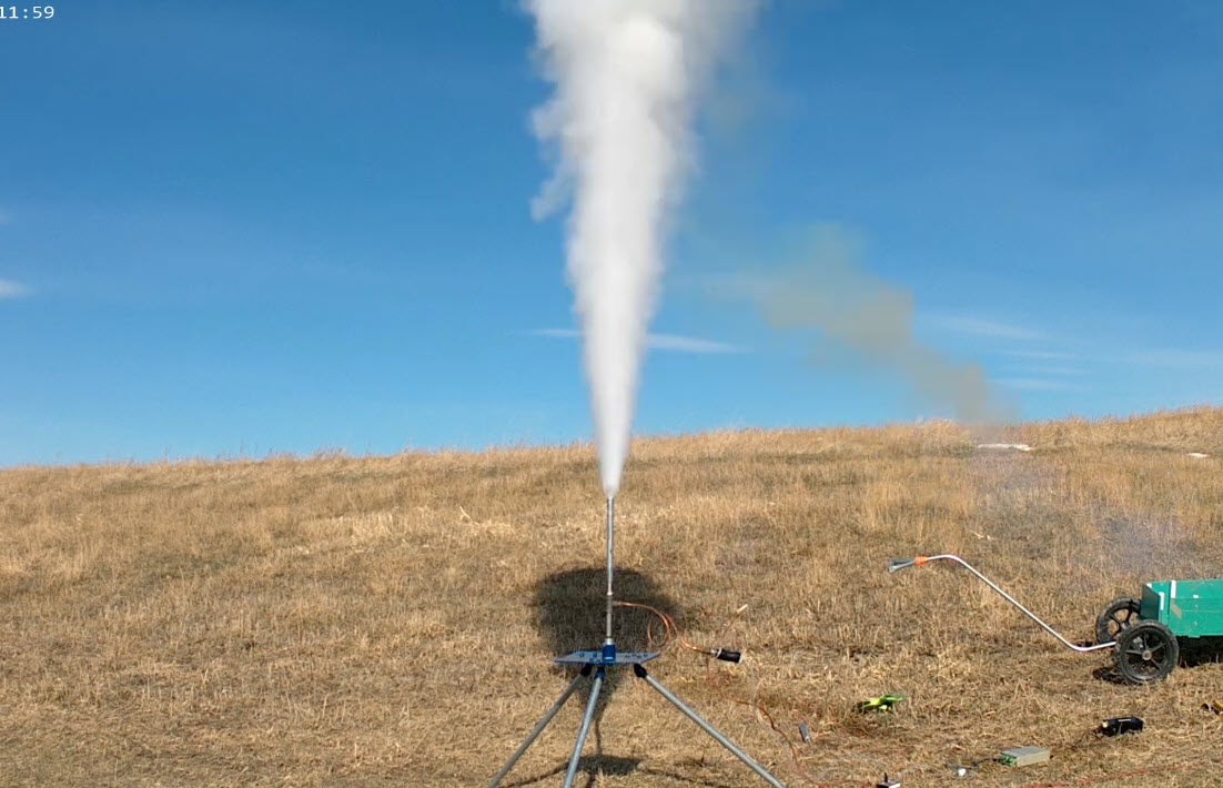
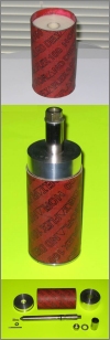
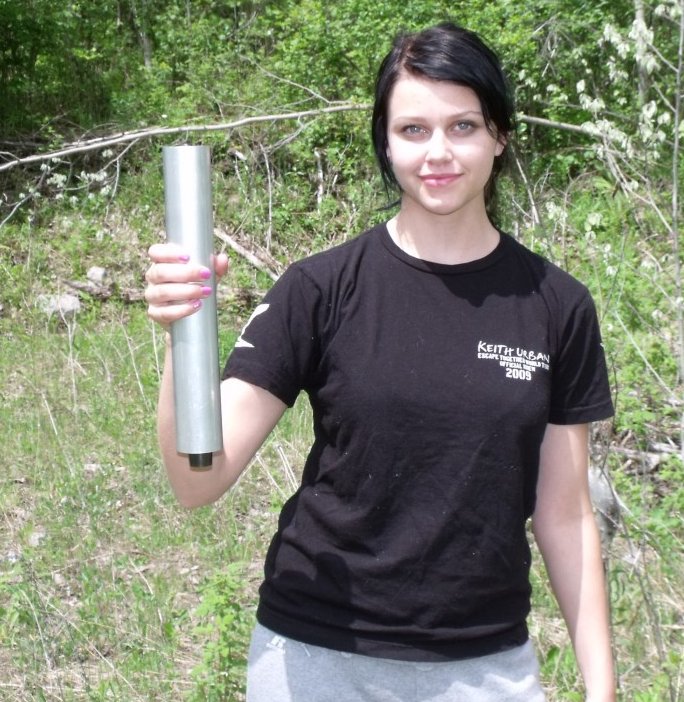
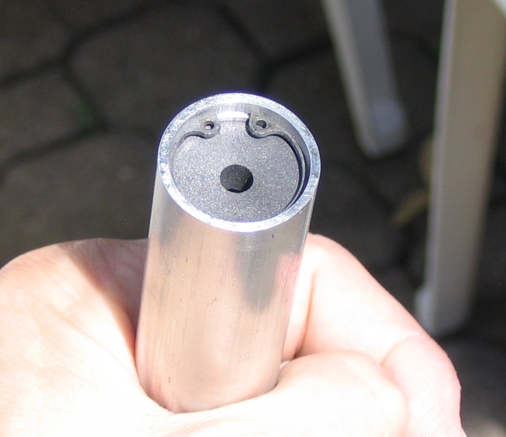
JEM rocket motor
| July 17, 2019
It has been over a year since I last updated my Sneak Preview page. As such, it is clearly time to tell about the many yet-unpublished projects that have occupied my spare time over that duration. Most recently, I have gotten a 3D printer. I figured it would be handy to have, as many parts related to my rocketry hobby can potentially be made more readily using "additive manufacturing" technology, compared to conventional methods. I have seen parts made by other rocketeers and have been more than impressed. So I was itching to get one for myself. The printer I bought is a FLSUN Cube, which comes as a kit. It is quite large, with a 260x260mm bed and can print items 350mm tall. It took a while to assemble and even longer to work out the bugs, but just recently I successfully printed my first rocket part -- a nosecone to replace the existing one for my Xi rocket. It is fabricated of PLA plastic and weighs a third of the current nosecone which was machined out of a solid bar of delrin (which was a big job!). I subsquently printed a parachute piston and AvBay compartment. Other parts that I foresee being 3D printed in the near future are fins and avionics supports.
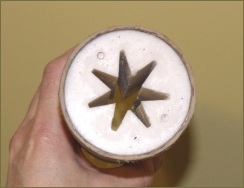
Wishing to further expand my rocketry horizons, last fall I began experimenting with AP (ammonium perchlorate) oxidizer and to a lesser extent KP (potassium perchlorate). Initially wanting to use a readily available binder, I began experimenting with silicone II. I was largely impressed with the results. Physically, the product blends well into a putty consistency perfect for packing into a mould. It cures effectively, taking about 2 weeks to mature into a nice rubber-like grain. I successfully static fired a number of motors using AP-Silicone II formulations. The burn rate was found to be very high. Although not necessarily a drawback, I have been investigating additives such as ammonium chloride in an attempt to tame the burn rate. Or alternatively, I might take advantage of the fast burn to design an end-burner motor. In the near future, I'll be experimenting with traditional APCP based on HTPB rubber. With regard to KP, I have found it to be a difficult beast to tame as a propellant oxidizer. This is not a great surprise as KP is known for its high pressure exponent and attendant problems. I have found that KP, when blended with other oxidizers, appears to behave in a more responsible manner. This is a promising approach that I have just begun to pursue.
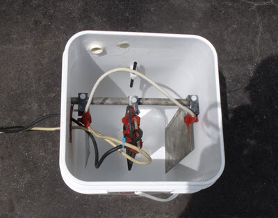
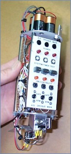
One of the essential elements of propellant development is determination of burn rate parameters (burn rate coefficient, a and pressure exoponent, n). This is useful for two important reasons. One, to ascertain whether the pressure exponent is in the practical range for a propellant (best between 0.3 and 0.6). And secondly, quantifying the burn rate parameters for a particular propellant is necessary for designing a rocket motor. A convenient device for measuring burn rate parameters is a strand burner. I have constructed a few of these in the past which have worked well. One of the drawbacks is the expense of using nitrogen gas as a pressurizing agent. As such, I decided to try designing and building a self-pressurizing strand burner. It seemed to make good sense to harness the combustion gases of a burning propellant strand to develop the required pressure. Another advantage to this approach recognizes that pressure changes (increases) as the strand burns, so theoretically a single burn can provide burn rate over a range of pressure.
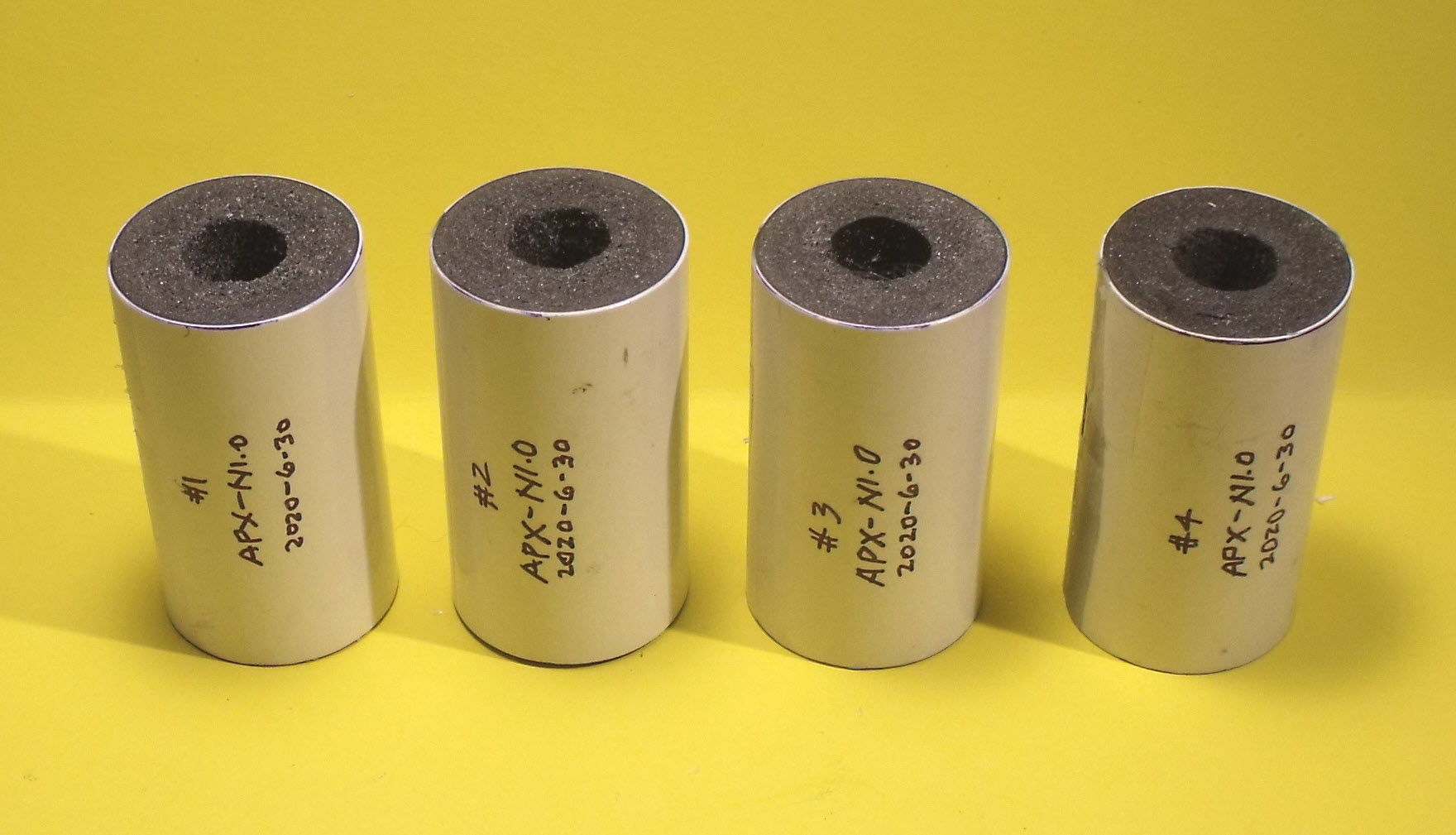
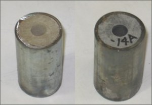
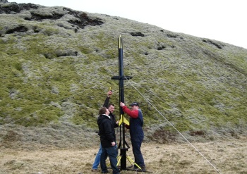
Venturing into another field of endeavour, I have recently flirted with nozzleless rockets. As the name implies, a nozzleless rocket is simply a rocket without a nozzle. Or more specifically, without a dedicated converging/diverging nozzle. The motor consists solely of a propellant grain cast into a casing, with a central core running the length of the grain. A bulkhead closes off the forward end. If such a motor is made sufficiently long, choked flow develops in the core. As such, the core serves as a sonic nozzle. After learning about the nozzleless development work of Serge Pipko and in particular the surprisingly decent performance of such motors, I couldn't resist trying nozzleless rockets for myself. I made a pair of 38mm motors, one KNSB based and the other KNDX. Each held just over 500 grams of propellant. Although the KNSB motor suffered an anomaly, ejecting the entire grain from the motor shortly after ignition, the KNDX motor performed well, burning for 2.5 seconds and producing a maximum thrust of 50 lbs. (220 N.). Subsequently this motor was successfully flown in my Xi rocket (Xi-9). Eventually I plan to delve into the theory of nozzleless flow to gain a better understanding of the physics behind it and to develop a rational basis for nozzleless motor design and performance prediction.
I've recently developed a new rocket motor for boosting the Xi rocket. My goal was to develop a motor with a slightly higher impulse and longer burn time than the workhorse Impulser. This new motor, deemed JEM, is a 51mm J-class motor powered by KNDX. JEM was first static fired on 4 January 2019. Following this successful test, the JEM motor boosted Xi-11 a little over a month later.
|

Static firing of the Impulser-XX
| June 27, 2018
Amongst other rocketry related endeavours that have kept me busy, I've recently worked on developing two new motors for my Xi rocket. One of these is a second stretch of my Impulser motor, which I've deemed Impulser-XX. This motor holds six grain segments of KNDX. This motor was successfully static test-fired on June 3rd. During the same outing, I test-fired my basic Impulser with KNSB. The purpose of this test was to assess certain design improvements such as grain inhibitor material and thermal liner that had an enhanced thermal protection coating. Also, an objective was to compare KNSB made with synthetic potassium nitrate (made from calcium nitrate) to that made with commercial-grade potassium nitrate (the Impulser-XX was likewise fueled by synthetic potassium nitrate). The results of these two tests demonstrated that synthetic oxidizer performed just as well. The enhanced thermal protection coating was also a success.
A third rocket motor, deemed SSJ-F was also fired -- a flight-version of a static-test motor that I'd developed and test-fired back in 2006-2007, the J-Class SSJ motor. This motor is slated to be flown in a future Xi flight. The test-firing of SSJ-F was less successful than the Impulser motor firings. A burn-through of the motor casing occurred shortly after achieving full thrust, leading to a partial rupture of the casing. Fortunately, no damage to the STS-5000 test stand or instumentation resulted, despite the violent event. Cause of the burn-through was, in hindsight, the result of a number of design flaws including deficiencies in the thermal protection. Of significant note, the SSJ-F did not incorporate the improved thermal protection used experimentally on the earlier Impulser/Impulser-XX tests. The SSJ-F motor is currently being prepared for a follow-up test firing in the near future, with several design modifications being implemented.
|


