STS-5000 Static Test Stand for Rocket Motors

|
|
IntroductionThis web page presents details on the construction of the STS-5000 Static Test Stand. This is an apparatus that I designed for static test firing of rocket motors. This test stand was designed to be versatile and capable of handling motors that produce up to 5000 Newtons (1100 lbs.) of thrust, such that sizes up to "M" class motors may be tested. This test stand was designed to be relatively simple to construct, using EMT (Electrical Metallic Tubing) as the main structural components. The "bolt together" design allows for simple construction, quick disassembly for transport and storage, as well as easy replacement of parts that get damaged when the inevitable CATO occurs.The STS-5000 Static Test Stand, as shown in Figure 1, was originally built for testing the Kappa Rocket Motor back in 2001. In the nearly 20 years since, the STS-5000 Static Test Stand has been utilized countless times for static testing nearly all my new motors. The basic design has remained largely unchanged. The only significant change from the original test stand design is the replacement of the tension rods with an adjustable chain-turnbuckle design, implemented for more convenient and timely setup in the field. As a pragmatic feature, the STS-5000 Static Test Stand test stand holds the motor in a vertical position, firing upward, such that the thrust force is reacted by the ground upon which the stand sits. This eliminates the complexities associated with horizontal firing test stands, such as the large mass (or other means) required for anchoring. Besides, there are no significant advantages to horizontal testing of motors. The weight of the motor (which rests on the load cell) can simply be subtracted from the measured thrust. In fact, the largest SRM ever built, the 260 inch diameter AJ-260X (SL-2) Space Booster was fired vertically in this manner. Originally, the STS-5000 Static Test Stand was fitted with a hydraulic load cell for motor thrust measurement. As the price and availability of electronic load cells and data acquisition systems have changed for the better in recent years, I now use a strain-gage load cell instead. In addition to a load cell for measuring thrust, I typically incorporate an electronic pressure transducer for chamber pressure measurement. Details on measuring chamber pressure can be found on my Measuring Chamber Pressure and Determining C-Star and Thrust Coefficient web page.
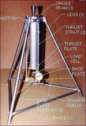 Figure 1-- Original STS-5000 Static Test Stand with Kappa-DX rocket motor, illustrating the main components ConceptThe basic structural form of the test stand is that of a tripod. A significant advantage to having three support legs is that the stand is self-leveling on any surface, with equal load distribution to each leg. The rocket motor is mounted vertically, nozzle upward, such that the thrust force exerts against the thrust plate. This plate sits atop the load cell, which bears against the Base Plate. The Base Plate is supported by a triangular arrangement of three Base Plate Supports which are attached at the ends to the three vertical Thrust Struts. These struts transmit the thrust load to the three Cross Beams. The tension load in the struts is beamed out to the three support Legs. The resulting compression load in the legs is then reacted at the ground surface. Wooden pads are placed under the foot of each leg to distribute the ground bearing load.The three Leg Braces prevent outward collapse of the legs. TheTension Rods serve to stabilize the structure against possible lateral loading that may develop during motor firing. The tension rods have recently been replaced by a chain-turnbuckle arrangement to facilitate setup in the field. Construction MethodEMT is used to make the basic structural components. To make the struts, the tubing is cut to length by use of a standard tube cutter, as shown is Figure 2a. A vise is then used to form the lug ends by simply squeezing the tubing end until flat, as illustrated in Figure 2b. A 1/4" hole is then drilled through the lug. The lug ends of the Leg Braces, Cross Beams, and Base Plate Supports are then bent at an angle, as shown in Figure 3. The lug corners may be clipped to eliminate the potential hazard of a sharp corner. Figure 4 illustrates the struts and Table 1 provides the strut dimensions.
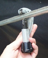 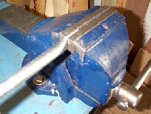 Figure 2a and 2b--Cutting the EMT to length, then squeezing the ends by use of a vise.
 Figure 3-- Lug end detail  Figure 4-- Struts (note that the Thrust Strut has end lugs that are at right angles to one another.  Table 1-- Tube cut and hole-to-hole dimensions The three tension rods are made from 1/8" diameter steel rod, with a "hook" formed at one end, and the other end threaded to accept a #5-32 nut, as shown in Figure 5. The hooked end is installed into a blind hole in the Leg, and the threaded end fitted through holes drilled through the Base Plate Supports. The nut is tightened such that the rod is under moderate tension. As an alternative to the tension rods, a chain-turnbuckle arrangement as shown in Figure 6 can be implemented. By rotating the shank of the turnbuckle, the tension in the chain is adjusted. This allows for simpler and quicker setup.  Figure 5-- Tension Rod
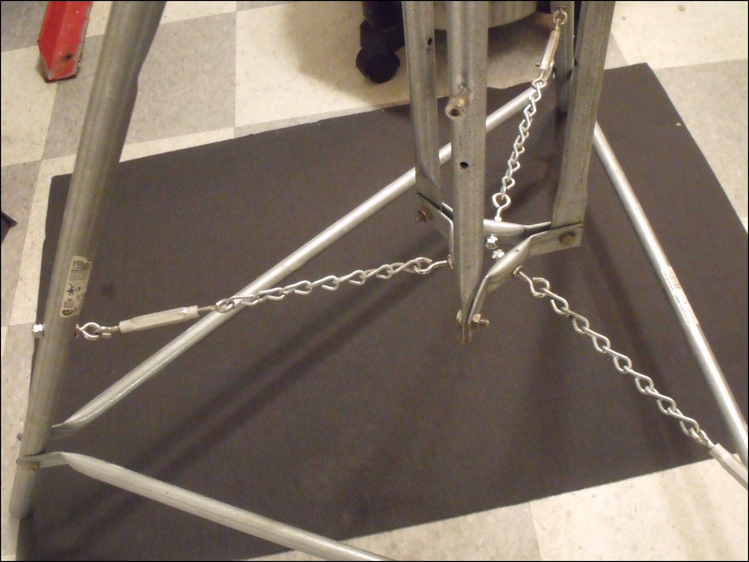
Figure 6-- Chain-turnbuckle arrangement as alternative to tension rods The various components are fastened together with 1/4" bolts as specified in Table 2. Machine screws (#10) are used as the nonstructural fasteners for mounting the rocket motor, Base Plate and load cell attachment brackets. Hardwood "mushroom plugs", drilled part way through to accept the #10 motor mount fasteners, act as motor guides. Two nuts, one on each side of the Thrust Strut, are adjusted such that these guides touch lightly against the motor. This allows for the slight downward displacement of the motor while firing. This arrangement is illustrated in Figure 7.
 Table 2--Structural fasteners  Figure 7-- Detail of motor mounting The Base Plate is made from a piece of 1/4" (6mm) steel or aluminum alloy plate. A triangular piece 4.75 in. (120mm) along each side is first cut out, then the corners cut off as shown in Figure 7. A hole may then be drilled, as required, for mounting of the load cell.
 Figure 7-- Detail of Base Plate
Construction detailsClick on thumbnail for larger image.
MiscellaneousClick on thumbnail for larger image.
|


