|
|
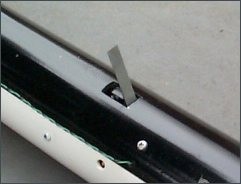
IntroductionThe concept of utilizing an Air-Speed Switch to trigger the parachute deployment system came about in the early years of my rocketry experimentation. After ill-fated attempts at other "apogee sensing" methods, I realized that by sensing the speed of air flow past the rocket in flight, this could serve as an ideal means to detect when the rocket approaches apogee. The solution seemed to be an air-speed activated switch, that is, an electrical switch with a spring-loaded external flap or vane that would deflect due to aerodynamic drag force. As the rocket would slow down near the peak, the spring would return the vane toward the undeflected position, closing the switch. This would then trigger the parachute ejection charge system. This concept proved to be, after several design iterations, quite successful. A later design incorporated a short delay timer (2-3 seconds), which allowed for a higher speed setting of the Air-Speed switch. The short delay allowed the rocket to slow further before triggering parachute deployment. A timer can also be incorporated to allow for delayed deployment of the primary recovery system. With such a system, the A-S Switch would activate a drogue system near apogee, which would allow the rocket to descend to a lower altitude before main parachute deployment, in order to minimize downrange drift of the rocket.There are a number of advantages to the Air-Speed (A-S) Switch system over conventional systems. Unlike a timer system, it is not necessary to have knowledge, beforehand, of how high the rocket is expected to fly (in order to set the time delay). The A-S Switch system is "automatic" and as such, it does not matter if the rocket undershoots or overshoots its target apogee. As well, the circuitry is much simpler and less expensive than either timer circuits or altimeter systems. More recently, the A-S Switch concept has been used with some of my contemporary rockets. The design of the switch, presented in this web page, is largely the same as the original switches. Two of these original switches are illustrated in Figure 1. Additionally, a simplified version of the A-S Switch is presented, which is easily constructed from a readily available type of "micro-switch".

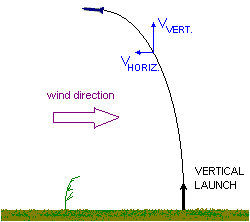
For a purely vertical flight, the rocket velocity drops to zero at apogee. For non-vertical flight (angled), the rocket will not achieve zero velocity at the peak, as it the rocket will maintain a certain horizontal velocity. The greater the trajectory angle as the rocket approaches apogee, the higher the horizontal component of velocity. This is important to recognize, and as such the triggering speed should not be set too low. Otherwise, the rocket may not slow down enough to trigger parachute deployment. Even if the rocket is launched vertically, weathercocking will tend to cause the rocket to veer into the wind, introducing a horizontal component to the trajectory, which can be quite significant (Figure 3). Therefore, a rocket equipped with a basic A-S Switch system should not be launched in windy conditions. This restriction can be eased by setting the switch to trigger at a higher speed, and utilize the optional timer element to delay deployment, as described in a later section of this article. For the basic A-S Switch design, I typically design the trigger velocity to be about 100 km/hr (60 MPH). For the A-S Switch design that incorporates a delay timer, the trigger speed is typically 150 km/hr (90 MPH) or higher. Weathercocking of the rocket can also be greatly reduced by lowering the stability margin of the rocket to the minimum required for stable flight (with an appropriate safety margin). The stability margin is the distance between the rocket's c.g. and c.p., and is given in terms of body diameter, or calibre. A stability margin of 1.5 calibre has been used for the Boreas 1 rocket, which was found to provide stable flight with minimal weathercocking.
Download CAD file.
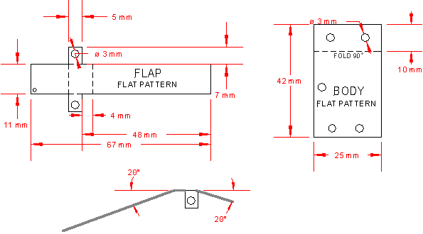
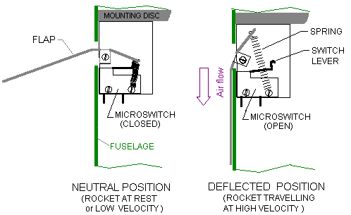
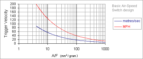
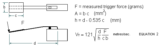
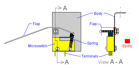 The spring is chosen to provide the required trigger speed of the A-S Switch. The trigger velocity may be estimated by measuring the force, acting at the end of the flap, needed to activate the micro-switch. The graph shown in Figure 6 provides an estimate of the trigger velocity versus the measured force (alternatively, Equation 1 may be used). The force may be measured by carefully pressing the flap end against a gram scale. Another means would be to tape a thread to the end of the flap and attach small weights to the thread until the switch activates. If the indicated trigger speed is too great, either the spring can be changed to one with less tension, or the flap may be cut shorter. The switch is mounted in the rocket as shown in Figure 2, necessitating a slot be cut in the fuselage for the flap to protrude, as illustrated in Figure 7. 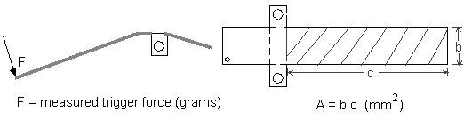 
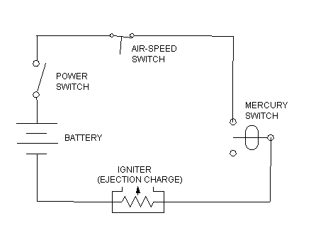 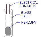
The mercury switch behaves as an inertial switch. After motor burnout, the mercury moves "forward" relative to the rocket, "shorting" the electrical contacts and thereby closing (activating) the switch. This behaviour is a result of the mercury being acted upon (decelerated) solely by gravity, however, the rocket itself is acted upon by both gravity and aerodynamic drag, causing the rocket to slow down at a faster rate than the mercury in the switch. As such, the mercury moves forward relative to the rocket, and (importantly) remains in the forward (activated) position throughout the remainder of the flight. Therefore, when the rocket slows sufficiently to activate the A-S Switch, the circuit is completed and power is then applied to the igniter of the ejection charge, firing the parachute deployment system. Mercury switches have been used extensively in the past for thermostats and as 'tilt switches' for appliances, and as such, are readily available. However, instead of using a mercury switch, any type of inertially activated switch may be used (note that mercury is toxic; in case of breakage, the mercury must be handled and disposed of by an appropriate means. MSDS). Figure 9 shows an enhanced circuit equipped with a Safe/Arm switch as well as an indicator LED to confirm the activated state. A Test & Arming Procedure allows for the LED to indicate a faulty or otherwise closed condition of the mercury switch (it has been found that on rare occasions, a small amount of mercury may get lodged between the two contacts, unexpectedly activating the switch). This design also allows for pre-launch testing of the complete circuit by inverting the rocket. The optional igniter continuity test circuit allows for checking of the igniter bridgewire.

Additional components required for the enhanced circuit are:
This simple version of the A-S Switch was devised, and has been used extensively, by fellow AER enthusiast Robert Furtak. In Figure 12, Rob is seen with a rocket, equipped with such an A-S Switch, that flew to an estimated altitude of 3500 feet (1 km.). It is important that the flap be strongly attached to the switch lever. As such, only structural grade epoxy (not "5-minute" epoxy) should be used to bond the flap, and surfaces of both the flap and the lever be cleaned with acetone, lacquer thinner or alcohol to remove all traces of oil or other contaminants.


Another timer based enhancement provides for a two-stage recovery system. With this system, the A-S Switch triggers deployment of a drogue recovery system at apogee. The drogue system has the purpose of allowing for a moderately rapid descent rate of the rocket. This is important for higher altitude flights, where downrange drift (due to even light breeze) can be great if the main parachute is released at apogee. The drogue system may be a small parachute, a streamer, or it may even be sufficient to "break" the rocket into two halves which would then have the tendency to tumble during descent. The timer that fires the main recovery system can be activated by:
The three different scenarios which utilize an A-S Switch for recovery system activation are shown in Figure 13.

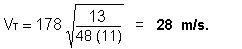
For the Basic A-S Switch, with a Flap of the dimensions shown in Figure 4, what is the estimated trigger velocity if the measured force applied at the Flap tip is 13 grams to activate the micro-switch? From Figure 6, the noted dimensions are b (11 mm) and c (48 mm). This gives A = b c = 11 (48) = 528 mm2 With a trigger force, F = 13 grams, the required ratio of A/F as used in Figure 6 is A/F = 528/13 = 41 mm2/gram. From the graph in Figure 6, the trigger velocity is therefore approximately 28 m/s or about 63 MPH.
Alternatively, Equation 1 can be used to obtain the trigger speed:
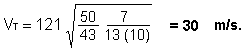
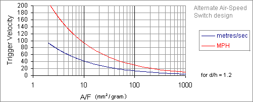
Example of estimating trigger speed for Alternate A-S Switch design. For the Alternate A-S Switch, with a Flap of the dimensions shown in Figure 11 with b = 10 mm and c =13 mm, and dimension d = 50 mm, what is the estimated trigger velocity if the measured force applied at the Flap tip is 7 grams to activate the micro-switch?
This gives A = b c = 10 (13) = 130 mm2 and With a trigger force, F = 7 grams, the required ratio of A/F as used in Figure 11 is A/F = 130/7 = 19 mm2/gram. From the graph in Figure 11, the trigger velocity is therefore approximately 30 m/s or about 67 MPH.
Alternatively, Equation 2 can be used to obtain the trigger speed:
Derivation of Equations 1 & 2 (zipped gif images, 300 kbyte).
|