Introduction
This web page presents details regarding the design of a strain gage based load cell that can be used, in conjunction with an electronic data acquisition (DAQ) system, for static thrust measurement of a rocket motor. The load cell described here is meant to be relatively simple to make, versatile to design with regard to load capacity, sufficiently accurate for its intended use, and inexpensive. The cost of a basic (single-gage) load cell made by this method would typically be no more than $10-20 USD. For a more precise four-gage loadcell made by this method, the cost would be about double this amount. Of course, the underlying reason for constructing a load cell isn't measured in "dollars and sense", but is part of the fundamental premise of Amateur Experimental Rocketry -- the challenge to fabricate, whatever is practical, from scratch.
I have made a number of loadcells using the method described here, and have utilized them extensively for thrust measurements of my motors, with excellent results.
Even for those who prefer to utilize a commercial load cell for thrust measurement, the load cell described here can be of great benefit as a "dispensible" tool for static testing of new designs (or modified designs) which inherently have a greater likelihood of catastrophic failure. With this inexpensive load cell, thrust data can be obtained on maiden firings of motors, saving the commercial unit for proven designs.
Design concept
The type of load cell that is being presented is basically similar to a bending beam type. When a force is applied to the load cell, the beam (or bridge) onto which the strain gage is mounted, is subjected to combined bending and axial compressive stresses. The bending stress is by far the dominant component, hence the term "bending beam". Importantly, the relationship between the applied force and the combined stress in the beam is linear.
The stress in the beam results in corresponding strain of the beam material, and also of the strain gage (which is bonded to the surface of the beam). Strain is defined as change in length divided by the original length. The relationship between stress and strain is linear, related by the Elastic Modulus (E) of the beam material. The electrical resistance of the strain gage is directly proportional to the strain, with the net result being that the output signal from the load cell is linearly, or directly, proportional to the applied load, simplifying calibration and use of the load cell.
An important feature of the load cell is that total displacement under load is very small. This is significant, as it nearly eliminates unwanted dynamic effects associated with mass and large displacement (e.g. spring) systems.
When I originally came up with the idea of making a load cell, I wanted to simplify the construction as much as possible, while meeting certain criteria. For one thing, a compression load cell is most appropriate for thrust measurement,. Another criterion was to minimize displacement under load, as I had had a problem with my earlier Static Test Rig which had utilized a strain gage mounted on a cantilever beam. The deflection for that system was significant enough under loading such that it proved to be necessary to add a hydraulic damper to eliminate oscillations.
What eventually evolved was the concept shown in Figure 1. The load cell consists of a block of metal (steel, alumininum or brass) with a single hole drilled through it. To generate the required bending strain, a slit is cut on one side to create a bending bridge on the opposite side, to which one or more strain gages are bonded. Two gages mounted side-by-side provide double the output signal (and thus double the sensitivity and resolution) of a single gage. A "full-bridge" (or Wheatstone bridge) arrangement uses a total of 4 gages, of which 2 "active" gages measure the strain, and 2 "passive" gages, which serve to balance the bridge. This full-bridge arrangement offers excellent sensitivity and when properly designed, minimizes adverse affects due to temperature changes. Mounting of the load cell is achieved by a single bolt which screws into a tapped hole at the base of the load cell.
Figure 1-- Diagram of Load cell

Figure 2-- Determining gage strain
The equation shown in Figure 2 gives the strain at the gage location (egage) in terms of the applied load, as well as geometry and the material property of the load cell body. As mentioned in the introduction, the strain is directly (linearly) proportional to the applied load, and is inversely proportional to the body thickness (t) and the elastic modulus (E). In terms of geometry, the defining parameters are the hole location (e), hole diameter (D) and the location (b) of the applied load (P).
Therefore, it can be seen that there are five geometrical variables that determine the strain of the load cell:
- Body width (B)
- Body thickness (t)
- Hole diameter (D)
- Location of applied load (b)
- Location of the hole (e).
- B/3 £ D £ 2B/3
- B £ H £ 1.75B
- B/8 £ t £ B/2
- b ³ B/2
The negative sign indicates that this is compressive stress. The term k is a stress concentration factor obtained from Figure 3, and units of measure are lb. or N. for force, and inches or mm. for dimensions.
Figure 3-- Stress concentration factor chart and table of allowable stress
The load cell should be designed such that the maximum body stress under full applied load is approximately half the Yield Stress (Fty) of the body material. This is to ensure that:
1. No permanent strain occurs to the load cell body which could affect its calibration.
2. To ensure good linear response of the load cell.
Recommended maximum stress values are given in Table 1.
Note that the limiting factor in the design of the load cell is the body stress. The strain gage stress (or strain) is never the limiting factor. A typical foil strain gage can take 1% strain (or more) without damage, which is at least double the strain that a steel or aluminum load cell body can handle without permanent deformation. For best results, maximum gage strain should be less than 2000 microstrain to ensure good linear response. A good target strain for design is 1500 microstrain.
Construction
Generally, a load cell will be designed based on available (on-hand) material, to minimize the amount of metal cutting. For example, the design might be based on an available bar of aluminum, which needs only to be cut to the required length. Therefore, it is only necessary to drill the body hole, cut the slot, drill & tap the mounting hole, and drill a shallow hole for the ball bearing. The ball bearing should be epoxied into position. Particular care should be taken with regard to the body hole. The location should be accurately marked out, then drilling should be done by drilling a series of progressively larger holes, to ensure that the location does not "drift" while drilling. The bottom mounting hole should be drilled at approximately mid-width, then tapped to the desired thread size. The slot is simply cut with a hacksaw.
The ball bearing is important because it precisely determines the load application point. A hardened steel ball bearing performs admirably in this role, as it has the inherent strength needed to handle large applied loads without getting damaged. If the ball should get damaged, it can be easily removed by moderately heating the ball, which will soften the epoxy sufficiently to allow the ball to be removed.
The active strain gage is mounted at the location shown in Figure 1. If two gages are used, they are mounted side-by-side. The gage is to be mounted with the grid lines running parallel to the long edge, as shown in Figure 1. The gages are bonded with cyanoacrylate or epoxy adhesive (epoxy is easier and perhaps more reliable). It is important to lightly sand the bonding surface with 600 or finer grit sandpaper, then to clean the surface with acetone or lacquer thinner. If a 4-gage arrangement is chosen, the two passive gages may be mounted anywhere on the loadcell body. However, th location shown in Figure 1 is recommended. Notice that the gages are mounted with the grid lines running perpendicular to those of the active gages.
It is simplest to use a strain gage with lead wires attached. The strain gages that I purchased did not have lead wires, rather, only a pair of solder pads, which were very tiny. Soldering the lead wires (I used 30 AWG wire-wrap wire) onto the pads was accomplished with the aid of a illuminated magnifier lamp. The strain gages which I used were OMEGA SG-3/350-LY43 (Cost=$45 USD pkg. of 10). A similar type, but with lead wires attached, would be KFG-5-120-C1-11L1M2R (Cost=$59 USD pkg. of 10). After bonding, the strain gage is covered with a protective layer of epoxy, immersing a portion of the lead wires, as well. For detailed instructions on mounting the strain gages, see Appendix.
| I have recently obtained a limited stock of strain gages and am making them available to anyone who wishes to experiment with construction of a load cell. Cost is $20 USD for a pack of 8 gages. For more information click here. |
250 lb. Capacity Prototype Load Cell
To test the concept, I decided to build a prototype load cell using a small block of 6061 aluminum alloy that I came across in my metal stores. Having need for a load cell of 250 lb. (1100 N.) capacity, I determined hole diameter, hole location, and load application point to achieve this goal, based on the dimensions of the block.
Dual active strain gages were used for good resolution, with two dummy gages forming a full-bridge arrangement.
The finished product is shown in Figure 4, with the design data shown in Table 2.
The maximum deflection under full load was measured with a "feeler" gage, and found to be a mere 0.0035 inch (0.09 mm).
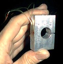
Figure 4-- 250 lb. capacity prototype load cell.
Table 2-- Design data for prototype load cell
200 lb. Capacity 4-Gage Load Cell
More recently, I decided to construct a load cell for thrust measurements of my new A-100M rocket motor. A load capacity of 200 lb. (900 N.) was considered to be ideally suited to the task. In order to achieve good accuracy under the expected variant of ambient temperature conditions, a 4-gage arrangement with 2 active gages and two passive gages was used. All four gages were of the same type. Temperature compensation was achieved by mounting all four gages in close proximity on the load cell body. The specifications for this strain gage type are:
- 350 ohm
- Constantan metal foil
- Phenol resin backing material
- 3 mm grid length
- Self-temperature compensation for aluminum
- Operational temperature -10o to 70oC
- Gage Factor 2.06
- Strain limit 2%
The four electrical leads coming off the strain gage bridge were attached to a 4-pin electrical connector. A connector ideally suited for this application is Radio Shack p/n 274-001 (which plugs into connector p/n 274-002). A couple of alternative connectors are available from Digi-key:
CP-1040-ND (plug) and CP-1240-ND (receptacle)
CP-1034-ND (locking plug) and CP-1234-ND (locking receptacle)
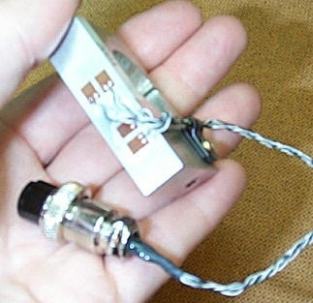
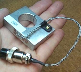
Figure 5-- 200 lb. capacity 4-gage load cell
(item below load cell is the electrical connector).
Table 3-- Design data for 200 lb. load cell
Here are some of the resulting thrust curves obtained from static tests of the A-100M rocket motor.
Calibration of load cell
The method used in calibrating the prototype load cell was similar to that used for calibrating the Hydraulic Load Cell. A 32 inch (80 cm.) lever arm was used to amplify an applied load of known magnitude. The applied load consisted of a container of water of known mass which was suspended at the end of the lever arm. An amplifier circuit was used to measure the resistance change of the strain gages as an increasing amount of weight was applied. The setup for the calibration test is shown in Figure 6, and the results of the test are shown in Figure 7.
An alternate method of calibration that is simple and accurate would be to employ a Hydraulic Load Cell to precisely meter the force applied to the strain gage load cell.

Figure 6-- Calibration setup for prototype load cell

Figure 7-- Calibration curve for the prototype load cell
Verification
In order to verify the design methodology, a number of 3-D finite element method (FEM) models were made of various configurations and capacities, utilizing a solid modeler software package. A typical model consisted of more than 1000 tetrahedron elements, with stress/strain results obtained by use of a NASTRAN solver. An example is shown in Figure 8, illustrating the stress contours.
Comparison of predicted gage stress was in good agreement with the FEM models. Prediction of maximum body stress tended to be conservative by about 10 percent.
Click for more details
Figure 8-- Verification FEM model of a 1000 lb. (4.45 kN.) capacity load cell. Stress range is shown, red is highest stress
Excel Spreadsheet
To greatly ease the design process, an Excel spreadsheet was created. The user simply need enter the desired load capacity, the basic dimensions of the load cell body, and the material. Subsequently, the hole diameter, hole location, and load application point may be chosen such that the maximum body stress does not exceed the values recommended in Table 1. An interactive pictorial of the load cell aids the design process. An example of the spreadsheet appearance is given in Figure 9.
Figure 9-- Sample Excel spreadsheet
Link to download Excel spreadsheet:
LOADCELL.XLS
Amplifier Circuit
Figure 10 shows an electrical schematic of the amplifier circuit that I have used in conjunction with the loadcell. As can be seen, the four strain gages (SG1 to SG4) are arranged in a "Wheatstone bridge" configuration. The output voltage of the bridge goes to the Vin+ and Vin- terminals of the INA122 amplifier chip. The output of the amplifier circuit (Vo and ground) are then connected to an Analog-to-Digital (A/D) converter (not shown). The A/D converter that I use is a DATAQ DI-154RS, which is a four channel, 12-bit unit that can sample at a rate of up to 250 samples/second. This unit comes with WINDAQ software which makes short work of analyzing collected data. DATAQ carries other affordable A/D units that are suitable, such as th DI-194RS.This particular circuit uses two 9V batteries for the power supplies. The voltage inputs to the INA122 are regulated by +5V and -5V voltage regulators. A single DPST switch is used for powering up the amplifier.
Figure 10-- Example strain gage amplifier circuit
| Item | Digi-key P/N | Quantity |
| Instrumentation Amplifier | INA122PA-ND | 1 |
| Positive Voltage Regulator, 5V | LM78L05ACZFS-ND | 1 |
| Negative Voltage Regulator, 5V | LM320LZ-5.0-ND | 1 |
| 1.0 microFarad capacitor | P2105-ND | 2 |
| Switch | SW102-ND * | 1 |
| Fixed resistor ** | -- | 1 |
| 9V battery strap connector | 2243K-ND | 2 |
** See discussion below.
Technical specs for all above parts are available from the Digi-key website.
Table 4-- Parts list for Amplifier circuit.
In the circuit, RG is a fixed resistor that is used to set the amplifier gain (voltage amplification factor). The procedure to determine the appropriate value of RG for a specific load cell design is described below.
- Calculate the maximum gage strain using the equation in Figure 2 (or obtain from spreadsheet).
- The change in resistance due to change in strain of a particular strain gage is given by its Gage Factor (GF). The voltage output (e) of the Wheatstone bridge arrangement of strain gages (which is inputted to the amplifier) is given by:
 where
where  , etc. are the values of strain of each gage, and E is the excitation voltage.
 - The required amplifier gain (G) can be determined as G = Vo/e, where Vo is the desired output voltage of the amplifier.
- From the INA122 data sheet, the required value of RG is given as
 , or rearranging to solve for resistance,
Determine RG for the 200 lb. load cell shown in Figure 5.
- The maximum expected gage strain, from Table 3, is 1778 microstrain (1778 x 10-6 in./in.)
- The Gage Factor for the strain gages is GF = 2.06 and the excitation voltage is E = 5.0 V. Since gages SG2 and SG4 are passive gages, their strain is always zero. Therefore the bridge maximum output voltage is given by

- Since the output voltage range of the amplifier circuit is chosen to be 0 to +5V, the required gain is
G = 5.0/0.009157 = 546 (see note below) - The required value for the gain resistor is therefore
Practical Guide
I recently created a guide to help those who have minimal experience is building and wiring circuits from scratch. This guide provides details on mounting and wiring the strain gages, as well as wiring of the amplifier circuit, and how to interface to a DATAQ unit.
Practical Guide to Wiring Load Cell and Amplifier
Appendix
Mounting Strain Gages on a Loadcell
Calculation of the Balancing Resistors of the Wheatstone Bridge is an on-line calculator to be used in conjunction with Roman's article. The script for this calculator was written by Lubos Kobes and Libor Ulcak and is provided here with their kind permission.
