|
|
IntroductionDevelopment work on the "J-class" Paradigm solid rocket motor began in November 2002. The motivation for developing a motor of this particular class was a perceived need for such a motor to serve as the powerplant for the first rocket of the Frostfire series. The goal of the Frostfire One rocket was to achieve a peak apogee of over one mile (1.5 km.). The design of the Paradigm was fundamentally different than all previous motors. Taking advantage of the unique attributes of the RNX epoxy-based composite propellant, it was decided to employ a grain configuration referred to "Rod & Tube". Such a configuration is comprised of a conventional tubular grain with a separate rod of propellant concentrically housed within. This has several advantages over conventional grain shapes:
To date, a total of four Paradigm motor firings have occurred, consisting of 2 static firings and 2 flights. The maiden static firing occurred on January 12, 2003 and was fully successful. The motor was modified slightly prior to the third usage, that being the Frostfire Two launch. Modification consisted of a slightly longer casing. The length was increased by 2 cm. The intent was to boost the Kn from the original 925 to 1020, to compensate for the cold temperature operation. Two RNX formulations have been employed for this motor, RNX-57 and RNX-71V. Due to the relatively low combustion temperature of the RNX propellants, a steel nozzle is fully suitable, and allows for unlimited reusability. The nozzle is cleaned after firing with the use of hot water to remove the potassium carbonate residue, followed by a soaking in muriatic acid to remove the crusty iron oxide deposits. The name "Paradigm" refers to the "prototype concept" of a fundamentally different motor design, in reference to the Rod & Tube grain configuration.
The Paradigm motor is capable of lofting an 10 lb. (4.5 kg.), 3" (7.6 cm.) diameter rocket to an altitude of about 5000 feet (1500 m.).
 
Right: Launch of Frostfire Two rocket with Paradigm motor in February 2004.
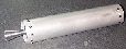
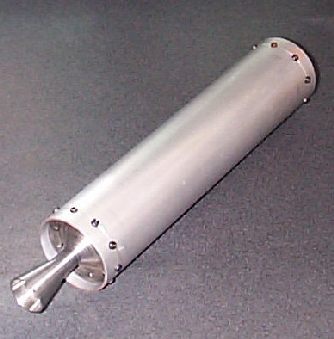
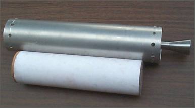
Basic DescriptionThe Paradigm rocket motor has basic dimensions of 2.5" (63.5 mm) outside diameter with an overall length of 13.25" (337 mm). The motor is constructed from aluminum alloy and steel components and is fitted with a standard conical profiled supersonic nozzle. The Rod & Tube propellant grain is closely fitted within the motor casing, inhibited on the outer surface of the Tube-grain, as well as at both grain ends. As such, the burning surface area remains theoretically constant throughout the burn, thus providing a completely neutral Kn profile (Kn = 925). Nominal propellant mass for the Paradigm motor is 930 grams (2.05 lbs) and the burn time is nominally 2.5 seconds. Either RNX-57 or RNX-71V potassium nitrate/epoxy propellant may be used in the Paradigm motor. The empty mass of the Paradigm motor is 570 grams (1.26 lbs).
A drawing of the Paradigm motor assembly is shown in Figure 3.
Click for larger image
A cross-sectional view of the Paradigm motor assembly is shown in Figure 4.
Click for larger image
A view of the motor with a cut taken through the propellant grain at is shown in Figure 5.
Click for drawing of complete motor assembly & components. NozzleThe nozzle is a conical profiled, deLaval supersonic type machined from low-carbon steel (SAE 1018), featuring 38o convergent and 12o divergent half-angles. The expansion ratio is 12:1, and typical operating pressure is between 900 psi and 1000 psi (6.2 MPa and 6.9 MPa), with MEOP being 1000 psi (6.9 MPa.). The nozzle is attached with ten #6-32 x 1/4" socket head alloy steel machine screws. Alloy steel screws are used due to their high shear strength of 95 kip/in2 (655 MPa). To provide an effective and redundant pressure seal, two -139 O-rings are used in conjunction with silicone grease. Standard buna-N (nitrile) O-rings have been used exclusively in the test firings conducted so far, with good results.For optimum performance, it is important that the inlet to the throat be well-rounded (radiused) to accelerate the combustion products more gradually. This reduces performance loss associated with two-phase flow velocity lag (see SRM Theory section for full details). The Paradigm nozzle is illustrated in Figure 6. |
BulkheadThe bulkhead is machined from 6061-T6 aluminum alloy stock. The bulkhead is attached with nine #6-32 x 1/4" stainless steel machine screws. These act as "safety shear bolts" that are sized to blow off the bulkhead in case of anomalous overpressurization (rather than suffering casing rupture). For sealing, the bulkhead is provisioned for two -139 O-rings, used in conjunction with silicone grease.The bulkhead as shown has provision for attachment of a pressure tap or alternatively for installation of a Delay Ejection Device (DED) for a parachute recovery system. When not being used, the hole can be closed off with a 1/8 NPT brass or aluminum plug. Alternatively, a "tether anchor" plug may be installed for direct attachment of the recovery system tether. The Paradigm bulkhead is illustrated in Figure 7.
CasingThe motor casing is made from 6061-T6 aluminum alloy tubing. The wall thickness of the tubing is 0.065" (1.7 mm), which makes for a lightweight casing. For a MEOP of 1000 psi, the design safety factor is 2.4, based on a tubing burst pressure of 2400 psi. The casing is thermally isolated by the Tube-grain during most of the combustion process. Toward the end of the burn, the cardboard inhibitor tube provides thermal isolation. It has been verified during static testing that following burnout, the casing is indeed cool to the touch.
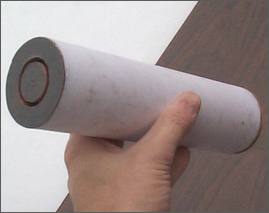
Casting/inhibitor tubeThe casting/inhibitor tube serves a number of important purposes. It is used as a casting form for the Tube-grain. Immediately prior to packing the RNX propellant, the inside of the casting tube is given a coat of epoxy adhesive. This ensures a positive bond between the propellant and the casting tube. The casting/inhibitor tube, which the name implies, also serves as an inhibitor by preventing combustion on the outer surface of the Tube-grain. An additional role that the casting/inhibitor tube serves is to thermally insulate and protect the motor casing during the final moments of propellant consumption and from residual heat following burnout.The casting/inhibitor tube is made from a single piece of posterboard rolled into a tubular shape around a forming mandrel. Typical thickness of the posterboard is 0.018" (0.5mm). The mandrel diameter is made such that two layers (plus a small overlap) of the posterboard will form the casting tube to a diameter such that it is a close sliding fit within the motor casing. The interply portion of the posterboard must be bonded with a suitable adhesive such that a final product is a monolithic tube. A surprisingly good adhesive for this purpose is "stick glue" typically used for bonding paper products. To create the casting/inhibitor tube, the posterboard should first be cut to a suitable size, with the length being such that approximately one centimeter protrudes from the top end of the casing when installed. This extra length allows for the casting tube to be taped to the motor casing (e.g. with masking tape). This is essential to prevent the casting tube from being pushed upward (and out of the mould) by the pressure resulting from the packing process.
Grain End InhibitorsTo achieve a theoretically neutral Kn throughout the burn, the ends of the Rod-grain and Tube-grain are inhibited. The aft-end inhibitors are made from cardboard, typically 0.025" (0.6 mm) thick. These end inhibitors are installed in the grain mould and as such, are bonded as part of the packing procedure. Prior to installing these inhibitors into the mould, they are given a thin coat of epoxy to ensure a positive bond to the propellant.The forward end inhibitor for both the Rod-grain and Tube-grain consists of a disc of 1/4" (6 mm) hardwood. The primary purpose of this disc is to serve as a support for the Rod-grain, however, a secondary function is that of an inhibitor. The support disc is epoxy-bonded to the two grains after the grains have been removed from the mould and cut to length. The support disc has a series of small vent holes drilled at the location of the gap between the Rod-grain and Tube-grain. These vent holes allow for rapid equalization of pressure all around the grain assembly at motor startup. This prevents structural loading of the grain due to motor pressurization. The support disc is illustrated in Figure 8.

Propellant MouldsThe mould for casting the Rod & Tube grain consists of four main components (Figure 9), which are assembled into a single unit. The mould for the Rod-grain also serves as the coring mould for the Tube-grain. To prevent propellant from bonding to the coring mould, it is wrapped over with a single layer of paper then spiral wound with a layer of either filament tape or packing tape (which does not bond to RNX).The motor casing serves as the female mould for the Tube-grain. The casting/inhibitor tube is fitted within this mould, and held firm with strips of adhesive tape at the top end. The Rod-grain mould is fitted with an internal spacer to reduce the inside diameter to 1.04" (26.4mm). The spacer is made from a length of tagboard (file-folder paper) concentrically wound to form a snug fitting tube within the mould. An appropriate sized mandrel helps to create the spacer, but is not essential. To prevent the propellant from bonding to the spacer, a single layer of thin, fine-mesh nylon or polyester fabric is bonded to the spacer prior to rolling it into a tubular form. Parachute fabric works well. Not only does RNX not bond to the fabric, after removal from the mould, the Rod-grain has a surface texture well suited to readily ignite. The fabric, being porous, also prevents air bubbles from being trapped (which would results in surface imperfections). Preparation of the grain mould is detailed in the RNX Composite Propellant -- Grain Mould webpage.

(casting tube, spacer and inhibitors not shown) Propellant GrainOnce the complete mould has been assembled (including installation of the end-inhibitors), enough propellant is prepared for packing the Rod-grain mould. Due to the limited pot life of RNX, the Rod-grain and Tube-grain are best prepared at separate times. A Tamping Rod is used to pack the propellant (which has a putty-like consistency) into the mould. Enough propellant is then prepared for the Tube-grain. Packing is achieved by use of a Packing Tool. Extra care is needed when packing the Tube-grain mould to prevent air from being trapped. Packing action should feel "solid" -- sponginess indicates trapped air.The process of packing the propellant in the mould is detailed in the RNX Composite Propellant -- Propellant Packing and Curing webpage. Note that one or two strands should be prepared from the propellant used for both the Rod-grain and the Tube-grain. These strands are later used to measure burn rate, as a quality control check. Once the Rod-grain and Tube-grain have fully cured, both are removed from their respective moulds, inspected, cut to length, then weighed and measured. A density check is then performed and actual density compared to ideal density. If the actual density is acceptably high, the grains are then assembled. This involves first drilling a shallow hole at the front end of the rod grain to accept a wooden dowel. The dowel is epoxied in place. At the same time, a generous layer of epoxy is applied to the forward end of the Rod-grain and all over the support disc (including the central hole). The Rod-grain, Tube-grain and support disc are then assembled and placed aside to cure. To ensure that the cantilevered Rod-grain is maintained perfectly concentric with the Tube-grain during curing, a couple of pieces of making tape are placed at the aft end of the grain assembly to hold the Rod-grain firmly centered within the Tube-grain. When the grain assembly is installed in the motor, it is important that the aft end of the Tube-grain seat firmly against the nozzle. Prior to installing, a generous layer of silicone RTV is spread on both the end inhibitor and the nozzle such that the grain is bonded with a pressure-tight seal against the nozzle. The purpose of having such a seal is to prevent hot combustion gases from seeping in between the casing wall and the grain assembly. The assembled propellant grain is illustrated in Figure 10.
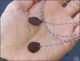
Motor IgnitionFor reliable ignition of the RNX propellant, a hot burning igniter must be used. Two types of igniters that have been used with good success are the Ferocious igniter, and the Spitfire igniter. The design and fabrication of these igniters is detailed in the Igniters & Ignition Systems webpage. The PDF article Nitrate-based igniters for composite propellant also describes a number of igniters that will function well with RNX propellant.The igniter must be prepared such that the pyrolant is formed into a thin disc, such that the igniter can be placed in the gap between the Rod-grain and Tube-grain. The igniter should also be placed at the forward end of the grain. Typically two igniters are installed, for redundancy, during installation of the grain into the motor. For safety, the igniter lead ends must be stripped and then shunted to eliminate any chance of inadvertent power application. Disc igniters are illustrated in Figure 11.
Engineering drawingsAcrobat PDF files
3-D ModelsThe following are three-dimensional renderings of the Paradigm motor and components. The models can be dynamically viewed and manipulated by use of the Solidworks eDrawing Viewer which is available as a free download. These models were expertly made by Mario Escalante who kindly granted permission to post them on my website.
     
Bulkhead Nozzle Casing Motor Assembly Grain Assembly Grain Support Disc Motor PerformanceThe Paradigm motor was designed with the aid of an Excel spreadsheet created for Rod & Tube motors using characterization data for the RNX propellants (Click for image). The design total impulse of 1030 N-sec. makes the Paradigm a 61% "J" class motor. Delivered specific impulse is 113 seconds. Design chamber pressure is 1000 psi (6.9 MPa) at Kn = 927.Actual performance numbers for the Paradigm motor have been obtained from static firings performed utilizing the STS-5000 test rig and electronic data acquisition. Both motor thrust and chamber pressure were recorded. Thrust was sensed with the use of a 200 lb. (900 N.) capacity strain-gage based load cell and pressure sensed using a 0-5000 psig Omega PX300 pressure transducer. The load cell was fitted with a full-bridge arrangement of strain gages, 2 active and 2 passive. Both were interfaced to a separate INA122 based instrumentation amplifier circuit, then piped to a DATAQ 154RS multichannel A/D converter. Data was collected and stored on a laptop computer. The pressure transducer was thermally protected from the hot combustion gases by a grease-filled manifold. Measured thrust and pressure curves are presented in Figure 12, together with the design values. 
Click for metric chart
The thrust coefficient was calculated using the measured chamber pressure, thrust and nozzle throat diameter. The initial values of thrust coefficient were lower than design, but tended to increase closer to the design value during the latter portion of the burn, as illustrated in Figure 13. 
|
