General Notes
The RNX propellant machines extremely well. This includes cutting, drilling, turning, facing, milling, sanding, filing and other such finishing operations. This simplifies the grain making process. For example, BATES grains may be produced by casting a single grain, then cutting into appropriate length segments. Propellant may be cast as a solid slug, and the core drilled after curing. As cast, a grain may have rough ends. These may be faced flat using a lathe, or by hand using a file or sandpaper.Cutting is best performed with a coarse (18 tpi) hacksaw. Sanding is best accomplished using medium grit paper or drywall sanding sheet. Adhesives such as epoxy and RTV silicone bond very well to RNX propellant, which is a useful trait that allows inhibiting to be applied to a finished grain, if need be. For example, RTV silicone or epoxy may be used as an inhibiting compound, or a cardboard inhibitor may be bonded to a grain.
Drilling the core
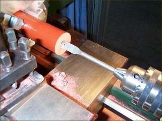
If a propellant grain has been cast as a solid cylinder, the core will need to be drilled out after curing is complete. Drilling is best performed using a Speedor bit, although regular twist bits also work well. Speedbor is preferred, as this style of bit provide generous clearance for the shavings to exit the hole. Twist drill bits may tend to pack the shavings, generating undesired frictional heat. The drill bit must be sharp. If the drilled out swarf feels hot to the touch (warm is normal), the drilling operation should be stopped, and the bit sharpened or replaced. A slow to moderate drilling speed should be used, with a light feed rate. As good safety practice, swarf should be continually collected and discarded in an attendant pail of water, and always have a bucket of water and fire extinguisher handy.
Cutting Fin Slots
The Pseudo-finocyl grain features slotted fins that project radially from a central round core. The core may be cast-in-place or drilled out. Once the core has been made, the fins may be cut using a saw blade. The first step is to mark, at both ends of the grain, the radial lines indicating the centreline of the fin slots. A mark is also drawn indicating the depth to which the slots are to be cut. To cut the slots, a coarse hacksaw blade (18 tpi) is used. For wider slots, two or more blades may be bonded together with epoxy adhesive. It is important that the grain be securely held in order to get clean cuts. I made a jig to hold the grain, using a length of channel aluminum onto which the grain could be rested. A second length of channel section is then placed on top of the grain. Clamps are then used to sandwich the grain between the channels, and to secure the assembly to a tabletop as shown in Figure 2.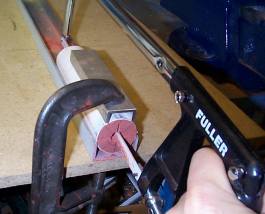

Figure 2 -- Pseudo-finocyl grain for the Epoch motor. This grain
was used for Flight Ze-2 of the Zephyr rocket.
It is important that the propellant be sufficiently cured to prevent gumming up of the blade teeth, yet the propellant should not be fully cured, as this makes cutting more laborious. I've found that a 24 hour cure at room temperature (25oC.) is about right.
Cast-in-place core
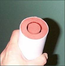
For those grains that have a cast-in-place core, the grain is nearly ready for firing after removal from the mould. The de-moulding process is illustrated as a series of steps in Figure 3. The core rod is first extracted, and should slide out with little effort. The filament tape is then pulled out of the core in an unwinding fashion. A hairdryer is next used to soften the hot-melt glue retaining the base. A box-cutter knife may then be used to cut through the glue allowing the base to "snap off". The grain is then extracted from the mould, again minimal effort is normally required.


Grains that have the outer surface inhibited are next cut into appropriate length segments that comprise the BATES grain. Such segments are illustrated in Figure 4, together with a Rod & Tube grain, which remains at its original length.
Grains that have the outer surface uninhibited will be glossy owing to contact with the plastic casting liner and as such will be epoxy-rich . The surface should therefore be lightly sanded to expose the oxidizer particles to aid ignition. If any surface flaws such as small voids are present, these should first be filled with 5-minute epoxy to eliminate the extraneous burning area.
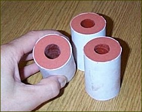
Rod & Tube grain (right)
Post-casting inhibiting
Although it is best to bond the inhibitor material during the casting operation, it is certainly feasible to inhibit the grain after curing. During the development of the Epoch motor, which utilizes an unrestricted cylindrical grain with only the ends inhibited, I applied inhibiting material to the cured grain. Silicone RTV and epoxy were both used effectively for end inhibiting. Both of these materials bond very well to RNX propellant. A drawback to these inhibiting compounds was discovered, however, during motor firing. Since the RNX propellants require a very high Kn, the nozzle throat is typically quite small. As such, it was noticed that fragments of the inhibiting material would naturally break away as the grain receded during the burn. Pressure spikes (accompanied by an audible "snap" or "pop" sound) resulted, sometimes double the MEOP. These pressure spikes are probably not harmful to the motor, as the spikes are of millisecond duration, but it is conceivable that a large enough fragment may, under certain conditions, cause damage. An example of a pressure-time curve is shown in Figure 5 which experienced pressure spikes as the epoxy inhibiting material was ejected from the nozzle. For this test, the grain ends (only) were inhibited with silicone-impregnated cotton fabric.

Figure 5 -- ERMS-2 static test results with characteristic pressure spikes
A good inhibiting material that does not produce such pressure spikes is thin cardboard, of 0.010" to 0.020" (0.25 to 0.50 mm) thickness. Cardboard tends to char and break away in tiny fragile fragments during grain surface regression and as such, does not cause any noticeable nozzle blockage. The cardboard inhibiting material may be bonded to the grain using 5-minute epoxy, applied to both the cardboard and to the grain surface. It should be secured flat against the grain while curing.
Control Strand
In the Propellant Packing section, mention was made and instructions were provided for producing a Quality Control Strand of propellant. This strand is used to help ascertain whether the propellant batch that was produced together with the strand turned out to be acceptable, based on ambient pressure ("open-air") burning rate. It has been found through my experience with RNX and other propellants that burn rate in the open air provides a good check of consistency from batch to batch.After the strand has fully cured, the straw is slit open lengthwise using a sharp bladed knife, and the strand removed. To help ensure even burning, the strand should have its surface inhibited with a coating of paint (hi-heat aluminum paint is best). Two "timing" marks are drawn on the strand using a pen. The distance between the two marks ("gauge length") is carefully measured and recorded. One end of the strand is sanded flat, then the strand is mounted vertically to a firm base using hot-melt glue, with the flat end on top. To perform the burn rate test, the strand is ignited on top, and using a stopwatch, the time duration for the flame front to traverse between the two timing marks is measured. The best technique for igniting the strand is to utilize a thin, flat metal bar heated with a propane torch. When red hot, the bar is pressed flat against the top of the strand. This ensures that the complete strand surface begins to burn at once.

Figure 6 -- Control Strand setup (left) and burning strand (right)
The measured burn rate is given by the gauge length divided by the time duration. For example, if the gauge length is 21 mm. and the measured time duration for the flame to travel between marks is 22 seconds, the burn rate is 21/22 = 0.95 mm/sec.
The flame should also be observed during the burn. It should burn at an even rate without any sputtering or tendency to self-extinguish. Small orange coloured "sparklets" that tend to shower forth from the flame are normal, as is the resulting residue that will accumulate around the base of the strand. Table 1 shows the expected range of ambient burn rate for the two propellants.
| Formulation | Ambient burn rate |
| - | (mm/sec) |
| RNX-57 | 1.00 +/- 0.20 |
| RNX-71V | 1.25 +/- 0.20 |
Density Check
The mass density of the propellant grain should be checked. This will give a good indication of the quality of the packing that was done. A density that is notably low may be a result of voids or other bubbles present in the grain. The presence of a small number of bubbles is generally not harmful. Due to the nature of the packing process, bubbles will migrate to the outside surface of the grain as the propellant is compressed during packing and will be visible after curing as surface voids (as mentioned earlier, the larger voids should be filled with 5-minute epoxy).The Theoretical Maximum Density (TMD) for the RNX propellants is as follows:
| Formulation | grams/cc | lb/cu.in. |
| RNX-57 | 1.869 | 0.0675 |
| RNX-71V | 1.848 | 0.0667 |
Density is given by grain mass divided by the grain volume. Volume is given by:

Where D or Do is the grain outside diameter, and Di is the grain inside diameter, L is the grain length.
As an example, consider an RNX-71V grain segment of 159 grams mass, Do = 4.5 cm, Di = 2.0 cm, and L = 7.0 cm. The calculated volume is 89.3 cc., with the resulting density of 1.780 gram/cc. The density ratio is therefore 1.780/1.848 = 0.95.
Measurement of density for an inhibited grain is, of course, complicated by the presence of the inhibitor. This should be taken into account when measuring both grain mass and grain volume. As such, the inhibitor weight should be measured and recorded prior to casting the grain. As well, an accurate measurement of the inhibitor thickness is required.
I have consistently obtained measured density of 93% to 95% of TMD for both the RNX-57 and RNX-71V grains. If the measured density is less than 92%, this indicates there may be a problem with the grain. This could be a result of:
- Voids present within the grain. Unfortunately, it is not feasible to determine if this is so without cutting open the grain.
- Formulation incorrect. Perhaps a weighing error during preparation.
- Vacuum processing not performed satisfactorily (RNX-71V only). Perhaps the bowl was insufficiently evacuated.
- Measurement or round-off error in determining mass density. Scale resolution should be no less than 1% of the grain mass. For example, if the grain mass is 100 grams, the scale should be capable of resolving 1 gram or better. Determining the precise grain diameter or length is often not possible and as such an average value must be used. Try remeasuring the grain dimensions with better precision.
Grain Handling and Storage
RNX propellant possesses excellent toughness (resistance to impact), nevertheless, care should be exercised in handling finished grains to avoid undetected cracks due to dropping or other inadvertent mishandling. Finished surfaces of propellant should not be touched in order to avoid oils from being absorbed, which could lead to local ignition delay. RNX propellant is not hygroscopic (does not absorb moisture from the air), so there are no special storage requirements. Finished grains should be placed inside a ziplock storage bag and put into a cool, dry, and locked storage cabinet. There does not seem to be a shelf life. I have burned samples of propellant that have been left in the open for over a year with no apparent degradation in physical properties or with respect to burn rate.
