|
The diameter of the hole should be such that the coring tool is a tight fit. A woodscrew is installed in the base to prevent the coring tool from displacing during the packing operation. A small hole is appropriately drilled into the coring tool to accept the screw tip. When applying the hot-melt glue, the casing should be adjusted such that the coring tool assembly is concentric to the casing (Click for sketch of setup). Unlike with the sugar-based propellants, simple lubricating of the core rod will not prevent the epoxy propellant from bonding, no matter how heavy the coating (another lesson I learned the hard way). After much trial and error, I eventually developed a very effective technique for coring tool removal. The coring tool is first wrapped with a single layer of writing paper, secured at the seam with cellophane tape. The length of the paper should be a few centimetres longer than the finished grain length. The width of the paper may be calculated as
 where Dc is the coring tool diameter. Glass-filament reinforced packing tape (e.g. Scotch® Filament Tape 897) is wrapped in a helical "barber pole" style around the coring tool, completely covering the paper layer. This seems to be best accomplished by wrapping two separate windings. The first layer leaves a gap that is covered by the second winding, as seen in Figure 4. where Dc is the coring tool diameter. Glass-filament reinforced packing tape (e.g. Scotch® Filament Tape 897) is wrapped in a helical "barber pole" style around the coring tool, completely covering the paper layer. This seems to be best accomplished by wrapping two separate windings. The first layer leaves a gap that is covered by the second winding, as seen in Figure 4.

Figure 4 -- First winding of filament tape around coring tool
The tape & paper are then trimmed off square at the bottom end such that the coring tool sits neatly into the base. After the grain has cured, the coring tool can be readily slid out of the paper sleeve. The tape is then extracted from the core by simply pulling at one end. As the filament tape has great strength (over 150 lb. tensile), removal is assured. From experience, it has been found that very little effort is required to extract the tape, as it does not bond to epoxy.
Two alternative methods of core casting have recently been suggested by my friend Roman. The first, which has been tested and found to work well, is to use a coring tool made from a metal rod covered by a vinyl tubing sleeve. Epoxy does not bond to vinyl, which is very flexible and is readily extracted from the cast grain after first pulling out the metal rod. To ease extraction, the rod is lubricated with grease. This mandrel assembly is illustrated in Figure 5.
Figure 5 -- Casting mandrel consisting of rod & vinyl tubing sleeve
Another alternative method suggested by Roman (currently untested) is to use a mandrel consisting of a metal rod that is dipped into molten paraffin wax. The wax forms a non-bonding surface on the rod. To extract the coring rod after the grain cures can conceivably be done simply by heating the grain to a temperature above the melting point of the paraffin. The rod should then slide out with little effort. Wax residue would need to be thoroughly cleaned off the surface of the propellant core to ensure ignition. This can be accomlished with mineral spirits, IPA, or similar solvent. This technique may also be suitable for more complex mandrel shapes, such as star or pseudo-finocyl.
BATES Grain
The BATES grain is similar to the hollow-cylindrical grain described above, with three key exceptions. One, the outer surface of the grain is inhibited. Two, the BATES configuration consists of two or more segments. Three, burning occurs not only at the core surface, but also on the ends of each segment. The number of segments and the corresponding segment length is typically chosen to provide a nearly-neutral Kn profile throughout the burn. A more thorough treatment of the BATES grain configuration may be found in the Rocket Motor
Design Charts page for the sugar-based propellants.
As with the hollow-cylindrical grain, the motor casing may be used as the mould. However, I have found it is better to have a purpose-made mould, cut to a length equal to (or slightly longer than) that of the desired grain length. This mould is made from the same tubing as the motor casing. Instead of using a spacer/liner, an inhibitor sleeve is required which fits similarly inside the casing. The propellant will be packed into this sleeve, and when cured, will be very effectively bonded to the propellant. For ease of fabrication of the inhibitor sleeve, the mould should be no more than marginally longer than the desired grain length. The core may be either drilled after curing, or cast-in-place. Figure 6 shows the casting mould, inhibitor sleeve, and coring tool, as well as the assembled mould ready for propellant packing.
 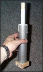
Figure 6 -- Mould components (left) and assembly (right) for casting BATES grain
The following is a suggested method of fabricating the inhibitor sleeve from a sheet of posterboard, which has a typical thickness of 0.020" (½ mm).
- Cut the posterboard sleeve to size (single layer thickness) allowing an extra 1 cm width for overlapping seam. The width (b in Figure 2) may be calculated as
 where Di is the mould inside diameter and bo is the overlap. Length, a, should be 0.1" (2 mm) longer than the mould. where Di is the mould inside diameter and bo is the overlap. Length, a, should be 0.1" (2 mm) longer than the mould.
- Using a mandrel that is of lesser diameter than the mould, roll the cardboard around it to "precurl" the sleeve (being careful not to make creases).
- Insert the precurled sleeve into the mould. Expand the sleeve tightly and using a pencil, mark the location of the seam (do this at both ends).
- Remove the sleeve, uncurl gently, and draw a line connecting the two pencil marks. This now defines the overlapping seam.
- Apply a generous layer of "glue-stick" onto the overlapping seam.
- Insert the sleeve back into the mould, expand it tightly against the mould walls, and apply pressure to the glued seam.
- Insert mandrel into the sleeve, place onto a firm flat surface (e.g. tabletop) and roll with firm downward pressure in a back-and-forth manner, as illustrated in Figure 7. This will serve two purposes: to bond seam, and to expand sleeve firmly against mould walls.
- Allow glue to dry before removal. If the seam has not bonded completely at the edge, use glue-stick to fill void, then tape seam with cellophane tape.

Figure 7 -- Rolling mandrel to expand and bond inhibitor sleeve seam
Rod & Tube Grain
The Rod & Tube grain configuration, as shown in Figure 1, consists of two separate grains, together which form a concentric assembly. There are a number of significant advantages to this configuration.
- As with the Unrestricted Hollow Cylindrical, the Kn profile is completely neutral (burn area remains constant). The BATES configuration is, at best, nearly neutral.
- Volumetric loading is excellent, better than either of the other configurations.
- The "Tube" grain serves as a thermal insulator, completely protecting the casing from exposure to hot combustion gases. As such, an aluminum alloy casing may be employed without need of thermal insulation. Both of the other configurations expose the casing to combustion heating, especially the Unrestricted Hollow Cylindrical configuration.
Although these advantages are substantial, the Rod & Tube configuration is best suited to larger motors (e.g. "J" class & up) simply due to the greater complexity of fabricating the grain and the requirement for customized moulding hardware.
The moulding apparatus is similar to that used for the other two configurations. The coring tool, however, serves an additional purpose. It is also the mould for the Rod grain. Figure 7 illustrates the moulding apparatus made for the Paradigm J-Class rocket motor.

Figure 8 -- Components of the Rod & Tube mould assembly
The following series of photos illustrate the various components of the Rod & Tube moulding setup:
(click on image for larger photo)

The inhibitor sleeve is made in essentially the same manner as the "spacer" required for the Unrestricted Hollow Cylindrical grain, using a mandrel about which to roll the sleeve. This method is more suitable than that described for the BATES inhibitor sleeve, as a double thickness of posterboard is used as a conservative measure. The mandrel is visible in the background of the photo.

The required Rod grain diameter is typically less than the inside diameter of the coring tool, as such, a paper spacer (plastic lined) is used to reduce the inside diameter. This is shown in the photo, as is the plug that seals the end of the coring tool.

The coring tool/Rod grain mould is covered with a single layer of paper, then wrapped with filament tape. The aluminum alloy tube that forms this component is mounted securely into the base. A cardboard cast-in-place end inhibitor disc for the Tube grain is visible.

Detail of the machined aluminum alloy base, which is fastened to the motor casing that serves as the mould. The base also firmly secures the Rod grain mould.

End inhibitor discs cut from 0.030" (0.75 mm) cardboard.

The inhibitor sleeve slides neatly into the mould (casing).

The assembled mould, with strips of tape applied to the inhibitor sleeve and spacer to retain these during the packing operation.
Pseudo-finocyl Grain
The Pseudo-finocyl (PFC) grain configuration, presented in Figure 1, consists of a hollow cylindrical grain, inhibited on the outer surface and having fin-like slots extending radially from a circular central core. Note that a true finocyl grain geometry is 3-dimensional. Specifically, the cross-section varies along the length of the grain, having a solely circular core at the forward end. The fins grow radially outward toward the aft end of the grain. A Pseudo-finocyl geometry is 2-dimensional, having the same cross-section throughout the length of the grain (note: "pseudo" = false).
- Unlike the other grain geometries presented earlier, PFC Kn profiles can vary greatly depending on the particular geometry of the fins and core. Five independant geometric variables allow for this: grain radius, core radius, fin width, fin depth, and number of fins. As such , it is possible to get a nearly neutral Kn profile. The PFC profile can also be tailored to suit particular goals, such as regressive for high initial thrust. It is also possible to have a profile that slowly tapers off at the end of the burn (as the slivers decay). This is ideal for producing a smoke tracking charge.
 
Figure 8 -- Charts illustrating example Kn versus surface regression that is
possible with a PFC grain configuration. On the left, an approximately
neutral burn. On the right, a neutral burn followed by gradual decay. Note: these charts were produced using the PFC-BURN Excel spreadsheet.
- Volumetric loading ranges from good to excellent.
- As with the Rod & Tube grain, the inhibitor serves as a thermal insulator, protecting the casing from exposure to hot combustion gases. However, the inhibitor must be more robust, as extended exposure of the inhibitor to hot combustion gases occurs locally where the propellant web first burns through (nearest the fin tips).
The mould for the PFC grain is identical to that of the BATES grain. The finned core may be cast by use of a suitable mandrel. However, the approach that I have taken is to cast or drill the circular core, then cut the fin slots. This technique is detailed in the section on Grain Completion.
|


