Richard Nakka's Experimental Rocketry Web Site


Kappa-DX rocket motor Static Test KDX-002
Test Report


  • Introduction
  • Motor Details
  • Static Test Rig
  • Test Report
  • Analysis
  • Performance
  • Conclusion
  • Introduction

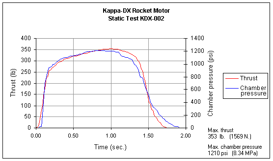
    This web page presents the test report detailing the second static test (KDX-002) conducted on the Kappa-DX rocket motor, as well as post-test analysis.

    Motor details

    The motor for this test was essentially identical to that of the first static test, except for the following modifications:

    • The casing liner consisted of a sheet of 0.0165 (0.42mm) inch thick posterboard paper concentrically rolled to form a double layer tube of a total thickness of 0.033 inch (0.84mm). This is identical to the liner used in the first static test. However, installation of the liner was modified. The liner was bonded over the entire overlapping surface by applying spray adhesive (3M Super 77) over the overlap region, after which the sheet was rolled over a mandrel to form a tube. The liner tube was then inserted into the casing (snug sliding fit) such that it would butt up against the nozzle. Silicone RTV was then applied to the tube end, and the nozzle installed. At the forward end, RTV was also used to seal the liner tube end, which extended to within a centimetre of the bulkhead. The short section of exposed casing was coated with silicone grease.

    • The propellant inhibitor was modified. Instead of resin coated paper, resin soaked fabric was used. The fabric was lightweight cotton, of 0.008 in. (0.20mm) thickness, and was cut to size to form a double layer around the segments. The process of inhibiting the segments was to first coat the segment outer surface with a layer of polyester/styrene resin, the carefully wrap the resin soaked fabric tightly around the segment. After setting, the inhibitor liner was trimmed and sanded smooth. As an extra measure, the liner was then sprayed with a layer of hi-heat aluminum paint.

    • The nozzle throat diameter was increased by 4%, to 0.495 in. (12.6mm), reducing the design pressure to 1110 psi (7.65 MPa). This was done to increase the safety margin between MEOP and burst pressure at elevated temperature.

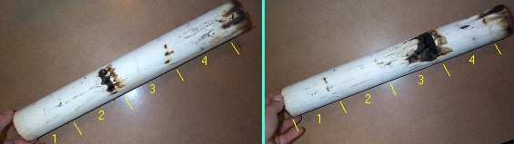
    • The four propellant segments had a total mass of 1497 grams (excluding inhibitor liners) and are shown in Figure 1. Core diameter was 0.75 inch (19.05mm) and typical O.D. was 2.21 inch (56.2mm).

    As with the first test, in order to substantiate structural integrity and effective sealing, the assembled motor was hydrostatic pressure tested to 1500 psi (10.3MPa), which represents 135% design pressure.

    Segments

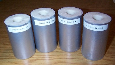
    Figure 1-- Propellant segments


    Static Test Rig

    The STS-5000 Static Test Rig was used once again for this test, with both gauges re-calibrated. Both thrust and chamber pressure were measured. Thrust was measured by use of a hydraulic load cell connected to a 4" 0-1000 psi pressure gauge. To measure chamber pressure, the motor bulkhead was tapped with a pressure fitting which was connected to a 4" 0-2000 psi gauge. To prevent damage to the gauge by hot combustion gases, the connecting line was filled with oil (SAE 30). Gauge readings were recorded by use of a video camera located 10 feet (3 metres) away. A plexiglas shield protected the camera from possible debris in case of a motor malfunction. As well, the shield buffered the camera from the shock waves due to the supersonic flow exiting the nozzle during normal operation.

    The rocket motor set up in the test rig is shown in Figure 2.

    Author with rocket in test stand

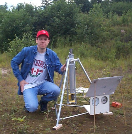
    Figure 2--Rocket motor set up in Test Rig just prior to conducting test


    Test Report

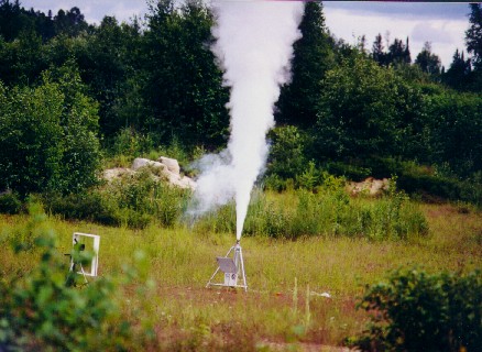
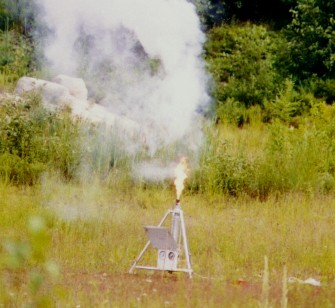
    July 22, 2000 -- After arriving at the test site, the test stand was assembled, having been partly dismantled for transport to the site. The motor was installed, connections to the chamber pressure gauge were made, and the oil buffer system was filled. Two video cameras were set up into position - one was used to record the two pressure gauge readings, the other was set up about 75 feet (23 metres) away to record the actual motor firing. A 35mm still camera with 135mm telephoto lens and autoadvance was also used to record the firing, from a distance of about 100 feet (30 m.). The autoadvance, which was activated just prior to ignition, allowed for continuous shooting of photos at a rate of 2 frames per second.

    Once the setup was completed, and the observers located a safe distance away from the test stand, the countdown was commenced. The igniter did not fire on the first attempt. Connections were checked and a second countdown was begun (the problem later was determined to be low battery charge). Shortly after the ignition button was pressed, a "pop" sound from the igniter charge was heard, and the glass-wool nozzle plug was seen to be ejected upward. Less than a second later, the motor roared to life with a deafening sound, and appeared to be functioning well, with a very large and well-shaped smoke plume. The sound of the exhaust jet undulated slightly. The burn continued for about two seconds, then rapidly tailed off. Blackish smoke then issued from the nozzle, and about a second after burnout, a bright yellow/orange flame erupted, as the vapourized residue in the motor ignited. The flame quickly reduced in size and was extinguished by an observer (by simply blowing it out).Two frames taken with the 35mm camera are shown in Figure 3.

    Motor firing  Flameout

    Figure 3-- Left: Motor at full thrust (small cloud is from ignition charge)
    Apparatus at left is videocamera for recording gauge readings, protected by plexiglas shield.
    Right: Flame from vapourized inhibitor, after burnout.
    Click here to download a videoclip of motor firing ( 7.7 Mbyte)...

    Click here to download a videoclip of test gauges during motor firing ( 5.9 Mbyte)...

    The Static Test Stand with hydraulic loadcell and chamber pressure monitoring system functioned perfectly. The videocamera captured both gauge readings clearly. The second videocamera captured the firing well, and playback showed that the smoke plume twice turned momentarily black, near the end of the burn. It is suspected that inhibitor fragments were being ejected. The consequence would appear to be harmless, as no pressure spikes were noted from the pressure data.


    Analysis

    In order to obtain an estimation of how hot the casing got during firing, two strips of "thermal sensitive tape" (Brother M-Tape) were placed around the casing perimeter. One strip at 4.8 cm. from the casing end nearest the nozzle, and the other 12.8 cm. from the same end. The first location was expected to be the region of the casing that would experience maximum heating (being adjacent to the nozzle inlet). Immediately after firing the motor, the strips were examined. The first strip was completely blackened, and slightly melted. The second strip was still completely white. However, over the following minutes, this strip turned totally black as well, as heat soaked through from the motor interior. The tape reportedly begins to decompose at a temperature of 365 C., therefore, the casing temperature reached approximately this level. The maximum design (target) temperature was 150 C., so this was clearly exceeded in (at least) this localized area of the casing. The entire casing was found to be hot "to the touch", but otherwise appeared pristine. The nozzle was entirely blackened, with the hottest region being where the throat meets the divergent section. The inside of the nozzle was coated with white residue. No leakage of any sort was visible at either the nozzle or bulkhead.

    When the motor was opened up for post-firing inspection, the insulating liner was found to be burned quite severely. In a number of locations, the liner was in fact perforated (see Figure 4). Combustion gases had impinged upon the casing walls at these locations, but upon close examination, it was apparent that no damage had occurred to the casing as a result. Clearly, burn-through must have occurred at the final moments of the firing, allowing the casing to dissipate the heat. Interestingly, and not surprisingly, the perforations coincided with the ends of the segments.

    spent liner

    Figure 4--Casing liner (alternate sides) showing burn-through regions at segment ends. Yellow lines mark the ends of each segment location (#1 is nearest the nozzle).

    The casing outside diameter was measured at several locations; no permanent deformation was found to have occurred.
    The nozzle showed negligible erosion of the throat, measured to be about 0.001 in. (0.025mm). The aluminum alloy bulkhead was in good condition, with no heat damage. The aluminum ignition canister, however, was badly burnt and had the porous appearance of "lava rock". It appeared to have reacted chemically with either the molten inhibitor resin or with the combustion product (liquid potassium carbonate), which would have fallen into the canister during the burn. It is also possible the aluminum reacted with the ignition charge combustion residue.

    The buna O-rings that sealed the nozzle and bulkhead again performed flawlessly. Careful examination of the O-rings confirmed that there was no blow-by whatsoever. The cross-section of the rings, however, was no longer circular, but flattened on two opposing sides, most certainly due to the heat "soaking" in the minutes after burnout.


    Performance

    Figure 5 shows a plot of the measured thrust and chamber pressure.

    Results graph

    Figure 5 -- Actual motor thrust and chamber pressure as a function of time

    As can be seen, the two parameters (curves) follow one another closely, as would be expected. Chamber pressure and thrust are related by the following equation:

    where F is the thrust, Cf is the thrust coefficient, At is the nozzle throat cross-sectional area and Po is the chamber pressure. The thrust coefficient is an important parameter which relates the amplification of the thrust due to gas expansion in the nozzle as compared to the thrust that would be exerted if the chamber pressure acted over the throat area only. In Figure 6, the thrust coefficient (calculated from the above equation) is plotted. The value of the thrust coefficient is seen to rise slightly with time, consistent with the theoretical assertion that it is a weak function of pressure.

    Cf graph

    Figure 6 --Nozzle thrust coefficient, shown over steady-state burn regime

    From the thrust-time curve, the total impulse of the motor was determined to be 2003 N-sec. (451 lb-sec.), which was very close to the design impulse of 2046 N-sec. The delivered specific impulse was a gratifying 137 sec.

    Figures 7 and 8 show a comparison of the actual thrust and pressure curves to the design (predicted) performance curves. The actual performance is strikingly close to the design curves.

    Comparison graph

    Figure 7 -- Comparison of actual and design thrust curves


    Comparison graph

    Figure 8 -- Comparison of actual and design pressure curves


    Note that the rise of the actual thrust (and pressure) curve is less steep than predicted. This is to be expected, and is a consequence of the fact that burning does not occur on all exposed grain surfaces simultaneously. Initially, burning occurs along the core, as the hot ignition gases flow toward the nozzle. Burning of the propellant along these surfaces then generates pressure within the chamber, forcing the hot combustion gases into the space between segments, thereby igniting the segment ends. This delay process may also responsible for the rather rounded shape of the steady-state curve, rather than (approximately) neutral thrust profile.
    Another interesting observation is that the initial erosive burning spike did not occur. The initial core-to-throat area ratio of 2.3 would appear to be sufficient to prevent erosive burning.
    The higher than predicted maximum pressure could conceivably be a consequence of nozzle slagging. Slagging is a build-up of condensed matter (molten potassium carbonate) on the nozzle, and in particular, throat surfaces. This effectively reduces the throat diameter to a slight extent, resulting in elevated chamber pressure.


    Conclusion

    The motor fully performed up to expectations, delivering a thrust and chamber pressure profile close to the design objectives. Total impulse was within 2% of the design goal, and the delivered specific impulse was very satisfactory.

    Clearly, a modification to the liner design is necessary to provide more effective insulating of the casing, which is essential to maintain the structural strength margin. The paper material does not stand up well to the chamber conditions of high temperature combined with extreme heating due to convection of the highly pressurized gases. A possible solution would be a single layer of material with good heat resistance (e.g. asbestos gasket paper) that would take the direct exposure of the combustion gases, together with the existing double paper layer that provides thermal insulation.

    The ignition canister, which suffered severe heat damage, also requires a redesign. In fact, even before this test, it was decided to modify the igniter design, in order to allow installation of the igniter just prior to firing the motor. With the current design, the igniter (and ignition charge) must be installed at the same time as the bulkhead is installed, which typically is done "on the bench". Even though the igniter leads are shunted (and remain so until just prior to firing), it was felt that, as a redundant safety measure, that the igniter should be left out of the motor assembly until the motor is mounted in the test stand (or rocket vehicle).


    Last updated

    Last updated Aug. 6, 2000

    Back to Home Page