
Experiments with Potassium Nitrate - Epoxy Formulations
|
|
|
|
IntroductionI first became intrigued with the idea of studying epoxy as a fuel/binder with a Potassium Nitrate oxidizer in late 2000, when I was given a sample of an experimental formulation by fellow rocketry enthusiast Marcus Leech. At that time, I performed some simple burn rate and combustion experiments which suggested that a Potassium Nitrate-Epoxy formulation might indeed have potential as a practical rocket propellant that may serve as an interesting alternative to KN-Sugar propellants. Due to involvement with other rocketry projects, I put aside further research until about eight months later. At this time, Hans Olaf Toft (ARL Library) sent me a draft copy of his own very interesting and encouraging experiments with Potassium Nitrate-Epoxy, which also suggested that a practical formulation could be possible (see Experiments with some KNO3/Epoxy Composite Propellants). The formulations that had currently been tried suffered from a variety of problems that prevented them from being a truly practical propellant. Such problems included very low burn rate, unstable combustion and large quantities of combustion residue which would be left over in the combustion chamber after firing (which is detrimental to performance). Combustion simulations done with GUIPEP indicated that performance of a Potassium Nitrate-Epoxy based propellant would be as good as, or better, than that of the KN-Sugar based propellants, especially if an additive such as aluminum was incorporated. Combined with the advantage of being able to 'cold cast' a propellant, Potassium Nitrate-Epoxy was sufficiently attractive that I decided to commence an extensive set of experiments beginning in September 2001. These experiments included measuring the characteristic velocity, also referred to as c-star (a key indicator of performance potential), burn rate at ambient and elevated pressure, physical property measurements, as well as three static motor firings. FormulationsIn total, 30 different formulations, identified as RNX series, were prepared (RNX-1 to RNX-30), of which the basis of all were Potassium Nitrate (KN) as the oxidizer and epoxy as the binder. Various additives completed the formulations: aluminum and sucrose as fuel additives, ammonium nitrate as supplemental oxidizer, and iron oxide, magnesium sulphate, copper sulphate as potential burn rate catalysts. Constituents
A summary of the thirty different RNX formulations is given in Table 3.
 Table 3 -- Summary of KN-Epoxy based formulations prepared for experiments Preparation of samplesAll samples of the RNX formulations were prepared as slugs, similar to the epoxy slugs shown in Figure 1. The first step was to prepare the "dry" constituents (e.g. KN, aluminum & iron oxide). These were accurately weighed (using a digital scale with 0.1 gram resolution) to the required proportions then placed into a polyethylene container together with 10-15 glass marbles. The container was then mounted on a rotating mixer and allowed to blend for 3 or more hours, depending on the batch size. Typical batch size was 60 grams (less the epoxy). Since many of the formulations contained aluminum powder, extra precautions were taken in handling of the blended samples, despite that fact that testing indicated that these dry mixtures were not combustible under ambient conditions.The epoxy resin and hardener were then separately weighed out, combined, and the dry mixture was then added, a small amount at a time, until all was incorporated. Samples were blended with either a table fork (small batches) or with a dough blender tool (larger batches) in a stainless steel bowl. The dough blender proved to be an excellent tool for this purpose, even for the larger sized batches of several hundred grams prepared for the motor tests.The blending operation typically took 15 minutes for a batch of about 75 grams. The resulting mixture had a puttylike texture which varied in viscocity depending on the degree of 'solids loading'. The thinnest was nearly pourable, and the thickest was like plasticine. The mixture was then pressed and compacted into a polyethylene container (35mm film canister) which served as a mould. Strand (stick) samples for burn rate measurements were prepared by packing the material into a polyethylene soda straw (the straw was 'dipped' into the material repeatedly until the desired length of straw was filled). The prepared samples were then allowed to cure for one or more days (see Figure 2). The utensils and bowl were cleaned using lacquer thinner. Due to the potential risk of epoxy sensitization, certain safeguards were conscientiously taken in the handling of epoxy resin and hardener, which included the use of a respirator with organic vapour filter (3M 6002/6001), and the use of vinyl (not latex) gloves. Polyethylene served very well as a mould material, as the epoxy does not adhere whatsoever to this plastic. The cured slugs were easily removed from the moulds by drilling a small hole in the bottom of the canister then using a small rod to push out the slug. For the c-star testing, the propellant slugs were then shredded using a rasp tool bit chucked into a drill press which rotated at 350 RPM. Special care and appropriate safety precautions were followed during this shredding operation, despite the acquired knowledge that repeated intentional 'overloading' by the rasping tool showed absolutely no friction sensitivity to ignition. The shredded material was then weighed out to 25 grams and loosely packed into a small plastic bag placed first into the combustion vessel. An electric igniter was also inserted, then the bag was sealed using a twist-tie. The intent of shredding was to provide for very rapid burning of the sample inside the combustion chamber of the c-star vessel. Rapid burning is necessary to minimize heat loss during the combustion process. Near-adiabatic burning is strived for, as any heat loss would tend to reduce the maximum pressure achieved by combustion.
 
Measured-to-ideal density ratio of the slugs varied from about 0.85 to 0.95 for those samples where measurements were made, as shown in Table 4. Its interesting to note that East epoxy had much better density ratios than West epoxy. This is evidenced by the comparison between RNX-3 and RNX-4, which have the same formulation, but different epoxy binder. Examination of cut & polished surfaces of these two samples under 30x magnification clearly indicated why the difference in density. RNX-3 (West) had many tiny pores (bubbles?), but the RNX-4 sample (East) had a complete absence of porosity.
 Table 4 -- Measured & ideal density for some formulations. Certain problems were encountered during preparation of RNX-26 and RNX-27. The addition of copper sulphate in RNX-26 resulted in a very slow cure, which took weeks. As such, only ambient burn rate measurements were made for RNX-26. When the RNX-27 dry mixture containing ammonium nitrate was added into the epoxy resin/hardener, a strong odour of ammonia was detected. The mixture was immediately discarded into the attendant water bucket, as a safety precaution. Burn Rate MeasurementsBurn rate measurements of the formulations at ambient pressure (one atmosphere), as well as at elevated pressure, was conducted on strands of propellant. For ambient testing, the strands were hot-glued to a wooden base in a vertical position. Typical dimensions of the strands were 0.25 inch (6 mm) diameter by 1-2 inch (25-50 mm) in length. For ambient pressure tests, gauge marks were scribed onto the strands to serve as timing marks. The distance between the marks was then measured and recorded. To conduct a burn rate measurement, the clocked time duration that the flame front traveled between marks allowed for calculation of burn rate. A diagram of the setup is shown in Figure 3
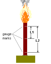
Burn rate for the strand was taken as the average of r1 and r2, where r1 = L1/t1, and r2 = L2/t2. Time duration t1 is the measured time required for the flame to traverse distance L1 and t2 is the measured time the flame required to traverse distance L2. All formulations had flames that were quite large and bright, with an orange-violet colouration. Those with aluminum content displayed white flamelets. All formulations produced a fair amount of white smoke, and most formulations produced a generous amount of carbon flakes.
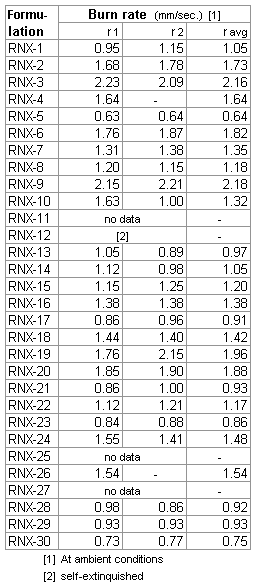 Table 5 -- Ambient burn rate results. For burn rate measurements at elevated pressure, the same apparatus used for c-star testing was employed (described in the next section). Before insertion into the pressure vessel, the length of the strand was measured and recorded. An electical igniter was fixed to the top end of the strand and coated with a BP/isopropyl alcohol (70%) slurry then allowed to dry. The strand was then mounted vertically (using hot glue) onto the closure fitting of the pressure vessel. The vessel was then assembled and sealed with silicone lubricant to ensure no leakage occured. The vessel was then pressurized with nitrogen to the required level of initial pressurization. During combustion of the strand hot combustion gases are generated, increasing the pressure. It was by this means the the burn time was determined. A video camera recorded the pressure during the burn. The burn time was taken as the instant the pressure began to rise, to the instant the pressure stopped rising. The effective pressure was taken as the average of the initial and final pressure (delta was typically 50-100 psi, depending on the strand length). Burn rate was calculated to be the strand initial length divided by the burn time. Three formulations were studied, being chosen on the basis of performance (c-star results) and practicality of the composition with regard to casting (some formulations were too 'stiff' to be considered practical). RNX-28 was tested first, and most extensively. The results are shown in Figure 4.
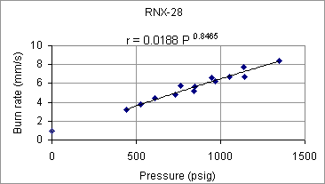 Figure 4 -- RNX-28 burn rate as function of pressure
The black line represents a 'best fit' power function of the form r = a P n , where a is the burn rate coefficient and n is the pressure exponent. As can be seen, the pressure exponent is particularly high (n=0.8465). It was felt that a high pressure exponent could result in unstable burning in a rocket motor, and as such, means of lowering the pressure exponent were sought.
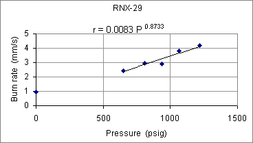 Figure 5 -- RNX-29 burn rate as function of pressure
It can be seen that iron oxide is clearly not the cause of the high pressure exponent, as the measured exponent was pretty much the same for this formulation (within experimental error). The effect of iron oxide, however, can be seen to greatly increase the burn rate by way of the burn rate coefficient. For example, at 1000 psig, the burn rate nearly doubles (r =3.5 mm/s for RNX-29; r =6.5 mm/s for RNX-28). 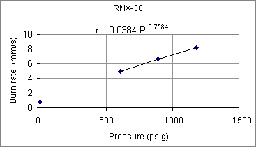 Figure 6 -- RNX-30 burn rate as function of pressure Although the pressure exponent would seem to be somewhat lower (n=0.7584), this could simply be due to the small sample size, as only three strands were tested. Indeed, even the obtained value would seem to be uncomfortably high for practical propellant useage. As a final note on the burn rate tests, the solid residue that remained of the strands varied from formulation to formulation, but in all cases the combustion appeared to be complete, including the aluminum. The residue consisted of a coral-like mass of what appeared to be mainly potassium carbonate and carbon. For those formulations containing aluminum, the residue included a white 'fluffy' powder characteristic of aluminum oxide.
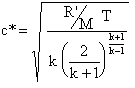
C-Star MeasurementsThe Characteristic Velocity, also referred to as Characteristic Exhaust Velocity or simply c-star (c*), is an important measure of thermochemical merit for a particular propellant, and is given ideally by
C-star is related to the Specific Impulse by the Thrust Coefficient, CF, and gravitational constant, g, (serving as conversion factor).  The CF quantifies the amplification of thrust performed by the nozzle. A simple 'hole' would have a CF=1. A well designed deLaval nozzle may have a CF=1.5 or greater.
For this set of experiments, c-star was measured by burning the propellant samples in a sealed pressure vessel, the so-called Closed Bomb method. The pressure developed in the vessel during the burn was displayed by a bourdon pressure gauge and recorded by use of a videocamera. The maximum pressure was then related to c-star, knowing the propellant mass and volume of the pressure vessel, by use of the following expression: 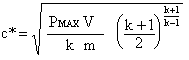 where V is the tank volume, and m is the mass of the propellant sample (for derivation, see page 1 & page 2). The volume of the pressure vessel was 0.927 litre, and the mass of each sample was 25.0 grams. The value of k was obtained from GUIPEP runs using the library entry for EPOXY 201. The data line (entry 383) excerpted from the pepcoded.daf file is shown below:
 which renders the following:
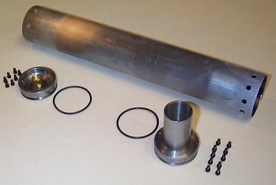
This was the only GUIPEP entry for epoxy. How representative it actually is of the epoxies used in my experiments in unknown. However, it is noteworthy that the sensitivity of c-star with regard to k is not great. For example, a 10% difference in k would only result in a 3% difference in c-star. As such, any inaccuracies introduced by the assumed epoxy properties should not be significant. The stated density is in close agreement with the measured density of cured epoxy samples, which had an average density of 0.0420 lb/in3 (1.16 g/cm3). This GUIPEP entry for epoxy was also used in the calculation of the ideal c-star value for the various formulations. Since ideal c-star is very much dependant upon the enthalpy of formation of the compound, the values obtained from GUIPEP are considered to be approximately representive of the ideal c-star for the actual epoxies formulations used in these experiments. To date, I have not been able to find any substantiation for the enthalpy of formation value given for Epoxy 201. The apparatus used in the measurements of c-star is shown in Figure 7 (also used for the elevated pressure burn rate measurements).
 The principle of operation is very simple. The shredded sample, confined within a plastic bag inside the pressure vessel, had combustion initiated by use of a tiny BP pyro igniter. The sample was consumed nearly instantly, and generated a rapid pressure rise in the vessel. The maximum pressure achieved was obtained from a video recording of the gauge during operation. Plots of the pressure measurements obtained are given in Figure 8.
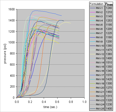 Figure 8 -- Results of combustion pressure measurements for RNX-1 to RNX-25.
As mentioned earlier, RNX-26 & RNX-27 were not tested. Samples RNX-28, RNX-29 & RNX-30 were tested in a slightly different manner, as explained later.
 Table 6 -- Measured and ideal c-star values for RNX-1 to RNX-25. Samples RNX-28, RNX-29 & RNX-30 were tested in a slightly different manner. For these three tests, the vessel was initially pressurized to 320 psig with nitrogen gas. This was conducted mainly to see if the higher initial pressure would result in a more rapid burn rate, and consequently more rapid pressure rise. The pressure curves obtained are shown in Figure 9.
 Figure 9 -- Results of combustion pressure measurements for RNX-28 to RNX-30. It turned out that the combustion rate (pressure rise) did not increase significantly due to the initial pressurization of the vessel. However, the delivered c-star for all three formulations, calculated based on the pressure delta, was improved appreciably in comparison to the formulations tested without initial pressurization, as shown in Table 7.
Why this is so is not currently understood. C-star is, theoretically, independant of the pressure at which combustion occurs. One more useful set of data that was derived from this series of c-star combustion tests is the rate of pressure rise, dP/dt . This is represented by the rising slope of each of the curves in Figures 8 and 9. This information is potentially useful for assessing the relative burn rates of the formulations, as least approximately. The maximum dP/dt value for each formulation tested is given in Table 8.
 Table 8 -- Maximum combustion pressure rise rate for the formulations.
Rocket Motor Static TestsIn total, three motor static tests were conducted utilizing KN-Epoxy formulations. A summary of the motor basic data is given is Table 9.
The predicted performance based upon the c-star and burn rate measurements was developed with the aid of SRM.xls motor design spreadsheet, and is shown in Figure 10. |


Figure 10 -- Predicted performance curves for the motors.
|
RNXS-1 The intent of this static test was to measure the chamber pressure developed by an RNX-28 grain combusting in a rocket motor. The motor was simple in design, utilizing steel (EMT) casing and a simple sonic nozzle, with a 19/64 inch (7.55 mm) throat. Four grain segments were used with a central 0.25 inch (6.4mm) core. The segments were free standing and uninhibited, providing a maximum Kn =580. A pressure gauge was interfaced to the motor to register chamber pressure, which was recorded by use of a video camera.
Static Test (29 October, 2001)
 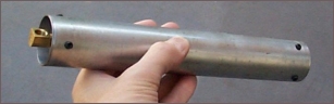 Figure 11 -- One of four grain segments, and motor, for RNXS-1.
RNXS-2
Static Test (3 November, 2001)  Figure 12 -- Propellant segments and motor for RNXS-2.
RNXS-3 The slab grains were cast using a steel channel as the mould, which was lined with PVDC film (Saran wrap) to allow for easy removal. The same motor that was used for RNXS-2 was used for this test, except that the casing was lengthened to accomodate the longer grain. A photo of the motor with the slab grain partly inserted is shown in Figure 13.
Static Test (11 November, 2001)  Figure 13 -- Propellant grain segments and motor for RNXS-3.
Mechanical PropertiesThe mechanical properties of the KN-Epoxy formulations are particularly appealing with regard to amateur rocket propellant requirements. When fully cured, the material can be readily "finished", for example, cutting with a hacksaw, drilling, milling, sanding, turning on a lathe, etc. There is essentially no tendancy for the "sawdust" to clog the saw blade or cutting bit, the way the sugar propellants do. Based upon a sizeable amount of such operations performed during this experimental work, inadvertent ignition resulting from friction sensitivity does not appear to be a problem (although necessary safety precautions are always mandatory). The material bonds well, which is important for application of inhibitors or for direct casting into tubes. The additonal fact that the material is non-hygroscopic eliminates handling and exposure limitations. As well, the fact that casting is done at room temperature eliminates problems associated with thermal processing, such as shrinkage. No measurements have been made of the tensile strength of any of the epoxy formulations, however, based upon "ad hoc" testing, it would seem to be greater than that of the sugar propellants. Importantly, even though the epoxy formulations fracture in a brittle (rather than ductile) manner, the impact resistance is vastly superior, with much of the impact energy being absorbed by plastic deformation at the impact zone. An estimate was made of the elastic modulus of the RNX-30 formulation. Elastic modulus, E, (also known as Young's modulus) is defined as the stress developed in a material at a given strain (analogous to a spring constant). This relates directly to the flexibility of a material, and for a rocket propellant, the lower the modulus the better. To measure the elastic modulus, the geometry of the slab grain prepared for RNXS-3 made for convenient measurement. The method is shown in Figure 14, whereby a force, P, is applied to one end of a cantilever beam (propellant slab) which is clamped at the other end, and d is the measured tip deflection.  Figure 14 -- Setup to measure elastic modulus For the propellant slab tested, which had a cross section of 0.46 x 1.41 inch (11.7 x 35.8 mm) and a cantilevered length of 14.57 inch (370 mm), the calculated value was E = 485,000 lb/in2 (3.34 GPa). This is very similar to the elastic modulus of plexiglas (acrylic), for which E = 450,000 lb/in2. ConclusionsA successful rocket propellant based upon a formulation of Potassium Nitrate and epoxy would seem to be an alluring, yet (so far) elusive goal. However, the work that has been performed so far has been valuable in gaining key insight into the behaviour of the epoxy based formulations. A summary of the traits of particular interest are given below:
Update
May 17, 2003 |


