
Thermal Protection for Rocket Motor Casings
|
|
|
|
A great deal of heat is, necessarily, generated by the combustion of propellant in a solid rocket motor. The hot combustion products are under high pressure and must be effectively and reliably contained by the motor casing to ensure the safe operation of the rocket motor. The casing behaves as a heat "sponge", continually absorbing heat, as essentially no heat is transferred from the casing outer surface to the surroundings (under flight conditions, however, some of the heat may be convected to the atmosphere) thereby continuously elevating the temperature of the casing walls over the operating duration of the motor. Fortunately, operating durations are usually quite short, as most structural materials suffer a significant reduction in strength at elevated temperature. Despite the short burn times, some form of thermal protection is usually required for the casing, as a result of the rapid transfer of heat that occurs in the "inferno" of high pressure turbulent flow conditions present in a rocket motor.
Thermal protection is generally not necessary, however, if all the conditions below are satisfied:
Item #2 is certainly the simplest approach. As will be shown later, materials with a high thermal conductivity (such as aluminum alloys) are capable of rapidly diffusing and "storing" any absorbed heat in such a manner that the overall temperature of the casing will remain reasonably low, as long as sufficient mass (i.e. thickness) is used.
Item #3 is probably the best approach to thermal protection for motors with high operating (combustion) temperatures and /or long burn times. An ablative material is usually a thermoset plastic or rubber material which decomposes (rather than melts) as it burns away. The material undergoes an endothermic (heat absorbing) degradation shortly after motor start, as the poor conductivity causes the surface temperature to rise rapidly. Pyrolysis gases produced upon decomposition provide additional thermal protection by forming a protective boundary layer.
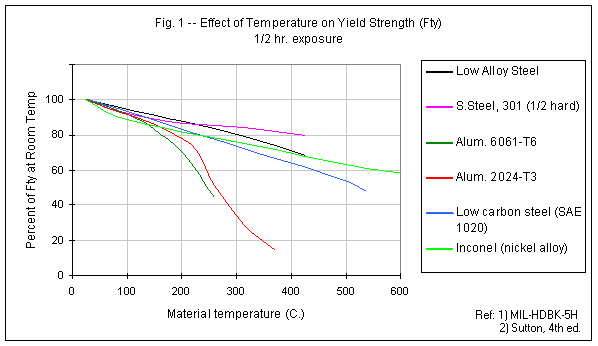
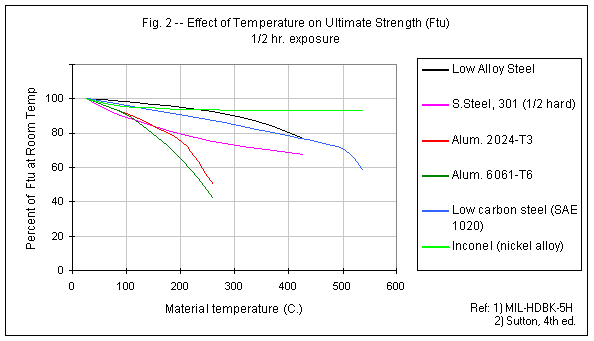
Both the material yield strength and the ultimate strength are similarly affected by elevated temperature. The yield strength (upon which design is typically based for reusable motors) is the stress level, which exceeded, results in permanent deformation, or yielding, of the structure. The ultimate strength is the stress level at which fracture occurs. The effect of elevated temperature on some casing materials is shown in Figures 1 and 2. It can be seen from these figures that aluminum alloys, in particular, suffer significantly even under moderate heating. For example, at 150 C. (300 F.), the 6061 alloy has only about 80% of the room temperature strength. For comparison, low-carbon (mild) steel retains 80% of its yield and ultimate strengths at 240 C. (465 F.) and 380 C. (720 F.), respectively. For reference, melting points are provided in Table 1.

| Low alloy steel | Stainless steel AISI 301 | Alum. 2024-T3 | Alum. 6061-T6 | Mild steel SAE1020 | Inconel |
| 1480 | 1400 | 500 | 580 | 1530 | 1400 |
Nearly all heat transfer from the hot combustion gases to the casing walls is through the mechanism of convection. This involves energy (heat) transfer due to molecular motion, or diffusion, combined with energy being transferred by the bulk motion (velocity) of the fluid. The convective heat transfer equation is expressed as :
This heat transfer is characterized by a large temperature gradient (drop) across a thin gaseous film adjacent to the casing inner wall and a temperature gradient through the wall thickness, the magnitude of which is dependant upon the casing wall material, in particular, the diffusivity of the material. This gradient can range from a nearly constant temperature, as heat is evenly and rapidly conducted through the wall, to a huge temperature difference between the inner and outer walls of the casing, for materials that are poor conductors. The convection coefficient, h, determines the rate at which heat may be transferred to the casing walls.
In order to study the temperature distribution, a FORTRAN program, THERMCAS, was written to calculate temperature at increments throughout the wall at 11 equally spaced nodal points, using the Schmidt method. Some results of this analysis are presented as an example. In Figures 4a,b, and c, as the time-varying temperature distribution through the thickness of a typical motor casing wall , for Aluminum alloy (2.5 mm wall), Stainless steel (2 mm wall) and PVC plastic (3.9 mm wall). In each chart, the 1st line (lowest) represents the initial distribution (t=0 sec.), and each successive line represents the distribution 0.13 seconds later. The topmost line is the temperature distribution at burnout (t=1.5 sec.). The thermal heating conditions for all three materials considered in this example are:


In order to better understand the results presented in the above charts, it should be noted from Equation 1 that the heat transferred to the casing wall is a function of the inner wall temperature, Ti. As the wall temperature climbs, less heat is transferred. Also,as mentioned, heat transfer depends upon the diffusivity of the casing material. The diffusivity (alpha) is the controlling property for transient (time-varying) diffusion of heat, and is given by

where k is the thermal conductivity, r (rho) is the mass density, and Cs is the heat capacity of the casing material. All three parameters are temperature dependant, although density change may be considered to be negligible.The room temperature values of alpha for the three materials presented are: [ units of m2/sec. (x107) ]
The effectiveness of thermal insulation in reducing the casing temperature is apparent by observing Figures 5 a,b. For this example, the insulation is 0.5 mm thick, with properties may be considered to be typical for a paper or thermoset insulator (alpha = 1.0). The casing is 6061 aluminum with 2 mm thick walls. The thermal heating conditions are the same as in the previous example.

A series of tests were performed of two insulation types: paper (rolled to form layers) and polyester coating. The purpose of testing was twofold: to study the behaviour of these two potential casing insulating materials under actual heating conditions; and to provide a measure of validation of the THERMCAS computer program.
The casing was represented by a section of 6061-T6511 aluminum alloy thin-walled tubing, identical to that which is being used for the kAPPA rocket motor (63.5 mm O.D., 1.65 mm wall). The paper that was used was brown "postal paper", with a measured average thickness of 0.15 mm. Two tests were conducted, one with 2 layers (0.29 mm) and one with 7 layers (1.0 mm).
The polyester was utility grade polyester resin, of the type used for automotive body repair (as a matrix for fibreglass). A single coating was applied to the inside of the casing and allowed to harden fully. To obtain a uniform coating, the casing was slowly and continuously rotated while setting. The measured final coating thickness was an average of 0.11 mm.
Two "control" tests were also conducted, with no insulation applied.
The setup for the tests is shown in Figure 6. A hole was cut into the side of the tube to allow entry of the propane torch flame, which was positioned such that the hottest part of the flame impinged upon the insulated wall (far side). A thermocouple (type K) was soldered to the casing outside surface, in direct line with the flame contact zone. To prevent combustion of the insulating material due to atmospheric oxygen, nitrogen was slowly fed into the test article via a hose and fitting near the base.
The thermocouple was interfaced to a computer for data acquisition, using a sample rate of 3 readings per second. To conduct the test, the torch was first ignited. A steel plate was placed between the flame and the test article to provide initial shielding. At t = 0, the shield was withdrawn, and recording of the casing wall temperature v.s. time commenced. The heating continued until the thermocouple detached from the article, as the solder attaching it melted. Examination of the paper insulation after each test revealed some charring of the innermost layer(s), but was otherwise intact. The polyester coating had no discernible degradation, other than some discolouration.
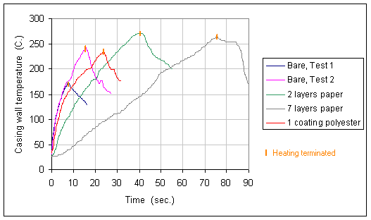
The results of the testing is summarized in Figure 7.


The test data was used in conjunction with THERMCAS to determine the experimental values of thermal conductivity of the paper and polyester insulators. It was first necessary to use the results from the non-insulated (bare) specimen to estimate the convection coefficient (h) associated with the heating process. This analysis was performed by a trial-and-error method of substituting in values of h into THERMCAS until the predicted temperature-time curve matched the experimental results. An assumed flame temperature of 1800 C. was used as input (flame temperature for propane with ideal air/gas ratio is 1967 C. ); predicted results indicated a low sensitivity to this parameter.
This analysis indicated a value of h = 55 Watt/m2-K. (it is important to recognize that this value is significantly lower than would be the case in an actual rocket motor, since the test was performed at atmospheric pressure. Under the high pressure of a rocket motor, the convection coefficient would be perhaps 20 or 30 times as great, and the heating times would therefore be much shorter).
The test results for the non-insulated test article are shown in Figure 8, together with the predicted heating curve used to estimate h.

After obtaining an estimate of the convection coefficient, it was then possible to use the test data for the insulated tests to derive measured values for thermal conductivity (k) of the layered paper and polyester coating. Mass density (r) for both the paper and the polyester were obtained through actual measurement. Measured values were: paper: 0.646 g/cm3; cast polyester: 1.26 g/cm3. Heat capacity values used in the analysis were obtained from published data. as were thermal conductivity values (to be used in comparison with the measured values), and density (for comparison only). The room temperature referenced values are:
| Material | Density | Heat capacity | Thermal conductivity |
| (units) | (g/cm3) | (J/g-K) | (W/m-K) |
| Paper | 0.930 | 1.34 | 0.18 |
| Polyester | 1.2-2.0 | 1.3 | 0.19 - 0.50 |
Results of the THERMCAS analysis are given in Figures 9, 10, and 11, with the derived k value shown.


The conclusion to be drawn from this series of tests is that layered paper and polyester coatings would both seem to be viable insulating materials for rocket motor casings. Both serve to significantly reduce the heat transfer to the casing walls. The behaviour of these materials under actual heating conditions is in reasonable agreement to that predicted by the thermal analysis technique used. Although the thermal conductivity values measured were somewhat higher than published values, the effectiveness is nevertheless apparent (part of the deviation can be explained by the fact that the measured values are the average over the temperature range, and are compared to room temperature values). It is interesting that the 7 layered paper insulation has a lower conductivity that the 2 layered. This is to be expected, as the trapped air between layers of paper provides additional insulation.
When sizing a rocket motor casing to handle the expected chamber pressure, it is important to consider the reduction in material strength at elevated temperature. Efficient design of the casing insulation usually allows for some degree of heating of the casing walls. The simplest technique to account for this would be to first determine the maximum average wall temperature (which will occur at burnout). Then using Figures 1 and 2 (or similar data), obtain strength values at this temperature, and size the casing to MEOP (max. expected operating pressure), using appropriate safety factors ( CASING.XLS may be used for this analysis).
A more refined approach would be to design the motor thrust (pressure) profile such that MEOP occurs early during the burn, while the casing walls are still relatively cool. The thrust profile would be regressive, such that the chamber pressure near burnout would be lower, to allow the heated casing to contend with lower structural loading.
Designing a motor casing of PVC plastic involves a different approach. The casing heats up appreciably near the inner surface, with the wall temperature rapidly dropping off toward the outer surface. The design approach would be to use a "knock-down" factor on the wall thickness. The effective wall thickness may be considered to be that thickness where the temperature remains below a certain threshold value. Since PVC begins to soften at about 100C. this may be used, for example, as the threshold value. Using the example of the non-insulated PVC casing shown in Figure 4c, the effective thickness would then be teff = (1-9/22) * 3.9 = 2.3 mm.
Download THERMCAS and companion Excel spreadsheet
THERMCAS.ZIP 62k Zipped DOS executable program and MSExcel97 spreadsheet
