Richard Nakka's Experimental Rocketry Web Site
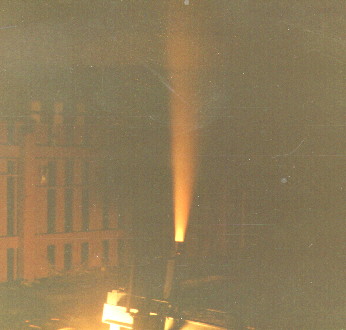
Static Test Rig was used on many occasions to obtain performance data on the B-200 motor.

Data aquisition system used in conjuction with Static Test Rig:
- Heath H-8 computer -- 8 bit, 8088 microprocessor
- Monitor and keyboard
- Dual Cassette tape recorders for data storage and playback on digital tape
- Voltmeter
- D.C. power supply
- Conditioning circuitry (voltage amplifier and A/D conversion)
- DVM
This was in 1982...today, all this can be replaced by a single multifunction meter!
Change in electrical resisitance in the strain gauges was converted to a binary signal by means of a conditioning circuit.
The motor thrust force (F) causes deflection bar, which is fixed at its ends, to displace downward. Displacement is limited by the lower stop; adjustable upper stop allows for setting of "zero" displacement. Right end support is adjustable to allow for different length bars to be used.

Thrust output in the form of voltage-time curves:LEFT: Static Test AST-2, March 28, 1982. which was one of the first rocket tests using the new Static Test Rig. The oscillations were a result of the Deflection Bar being insufficiently damped.
RIGHT: Static Test AST-4, April 16, 1982, same motor, but with Hydraulic Damper installed.
 Hydraulic Damper which was fitted to the Static Test Rig to eliminate oscillations. The needle valve allowed for considerable adjustment in the amount of damping this device provided.
 This plot of the thrust-time curve for the B-200 motor was made using data collected from a static firing on the Static Test Rig.
Back