In this web page, I am presenting details on the construction of a rocket fuselage from commonly available, light gauge, sheet aluminum. The type of sheet aluminum is the kind that is sold in rolls (20 in x 5 ft or 10 ft), or in bulk form, and is used for general purpose applications such as HVAC applications, or for automotive body repair. The cost is relatively inexpensive--I recently paid $19 CAD for a 10 ft. roll. The thickness of the sheet that I have used is 0.016 in (1/63 in.) which is #26 gauge. I have tried using lighter gauge material, such as #28 (0.013 inch), but found that it was too easily dented during handling. I would not recommend sheet lighter than #26 gauge for this reason.
There are a number of advantages to fabricating the rocket fuselages from sheet aluminum. First of all, aluminum tubing is often hard to obtain, especially in the larger diameters (> 2 inch /5 cm), and if it is available, the wall thickness (and therefore the weight) is much greater than is necessary for the application as a rocket fuselage. Machining the walls thinner is a lot of work and is not always successful, as I found that a crack will often occur along the butt welded seam once the wall is reduced significantly in thickness. Another advantage is that any custom diameter fuselage can be made by this method. My fuselages were typically 3 inches (7.6 cm) in diameter. Larger diameter fuselages can certainly be made with no problem. I have even made a sample fuselage with a diameter as small as 1-1/2 inch (3.8 cm) .
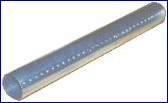
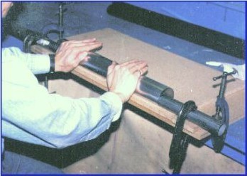
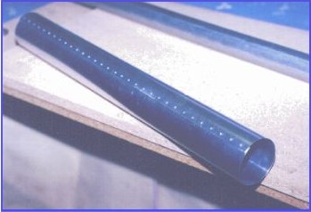
Two methods are presented. The first method is the technique I had used to construct the fuselages for all of the later rockets that I built. It involves forming the flat sheet to a cylindrical shape, then riveting the two edges as a lap joint, using blind (pop) rivets. This method is relatively simple, and produces a good final product. The disadvantage is the use of rivets, the heads of which protrude along the length of the fuselage exterior, causing parasitic drag. A way around this problem may be to use flat (countersunk) head rivets, rather than the dome (protruding) head rivets that are most commonly available. Since the sheet is too thin to be countersunk, it may be dimpled instead.
Another problem with rivets is that the formed head of the blind rivet protrudes along the inside of the fuselage, which takes up space and must be covered with a shield if a smooth inside surface is required, such as for the parachute compartment.
Although 3/32" rivets are the best, owing to their small head size, more commonly available 1/8" rivets will also work well. The rivet pitch (spacing) should be 5/8" (16mm) maximum.
When marking hole locations, use masking tape to make marks more readily visible.
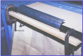
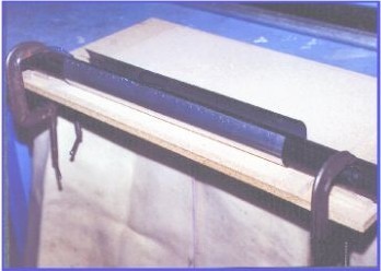
Moulds may be made from any suitable pipe that is reasonably rigid and will not deform when clamped. I have used iron water pipe, steel conduit tubing, and even ABS plastic sewer pipe (heavy walled). Most PVC piping would not be suitable, as the wall thickness is insufficient.
If the fuselage is quite long (eg L / D > 15), it may be desirable to install a stiffening disc near the middle section. This will stabilize the walls and provide assurance against column buckling. As well, it provides for a locally reinforced region of the fuselage that serves as a handling zone. This is illustrated in Figure 4. The reinforcing disc is cut from slightly heavier gauge aluminum sheet, such as 0.030 in (0.75 mm) thickness, with four tabs that are bent at a right angle, for attachment to the fuselage using rivets. The diameter of the disc should be slightly less than the inside diameter of the fuselage.
This is a project that I am currently working on. Instead of using rivets to fasten the lap joint, I plan to investigate the use of adhesive bonding. I will try both cold bonding, using an adhesive such as "liquid nails", and hot bonding, using structural hot glue (polyethylene). The obvious advantages are the elimination of rivet heads on the outside of the fuselage, and the elimination of the rivet formed heads on the inside of the fuselage, both significant advantages. Very preliminary investigation into this technique seems to hold out promise that such a method may work well.
