
Chamber PressureThe Chamber Pressure that a rocket motor develops is of crucial importance with regard to the successful operation of a rocket motor. Not only does Chamber Pressure strongly influence propellant burn rate, thermodynamic efficiency and thrust, the Chamber Pressure structurally loads the rocket motor casing and closures to a critical extent. Understanding the nature of Chamber Pressure generation, and accurate prediction of such, is one of the keys to successful rocket motor design. What causes pressure to develop inside the chamber of a rocket motor? What determines the magnitude of this pressure? Intuitively, the pressure buildup is a result of the combustion of the propellant grain, whereby the gases produced hasten to escape through the nozzle throat. If the throat is sufficiently small, the gases cannot escape quickly enough and the accumulation of gases in the chamber results in pressurization. In actuality, the intuitive explanation is essentially correct. However, an important factor that determines the magnitude of chamber pressure is not at all intuitive -- the concept of choked flow. This concept provides for a convenient means to calculate chamber pressure, and is valid for both transient and steady-state modes of motor operation, as discussed below. By looking at a plot of Chamber Pressure over the operating duration of a rocket motor (Figure 1), one sees that there are three distinct and important phases of operation:
 The pressure curve of the rocket motor exhibits transient and steady-state behaviour. The transient phases are when the pressure varies substantially with time -- during the ignition and start-up phase, and following complete (or nearly complete) grain consumption, when the pressure falls down to ambient level during the tail-off phase. The variation of chamber pressure during the steady-state burning phase is due mainly to variation of grain geometry (burning surface area) with associated burn rate variation. Other factors may play a role, however, such as nozzle throat erosion and erosive burn rate augmentation.
First of all, the start-up and steady-state pressure phases will be considered. The start-up phase is hypothetically very brief, although in reality, ignition of the complete grain does not occur instantaneously. The actual duration of the start-up phase is strongly dependant upon the effectiveness of the igniter system employed.
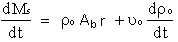
 equation 1 equation 1where  p is the propellant density, Ab is the grain burning area, and r is the propellant burn rate (surface regression rate). p is the propellant density, Ab is the grain burning area, and r is the propellant burn rate (surface regression rate).It is important to note that the combustion products may consist of both gaseous and condensed-phase mass. The condensed-phase, which manifests itself as smoke, may be either solid or liquid particles. Only the gaseous products contribute to pressure development. The condensed-phase certainly does, however, contribute to the thrust (overall performance) of the rocket motor, due to its mass and velocity, as shown in equation 1 of the Thrust Theory Web page. The rate at which combustion products are increasingly stored within the combustion chamber is given by: 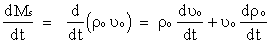 equation 2o is the instantaneous gas density in the chamber, and uo is the instantaneous gas volume (which is equal to the free volume within the chamber). equation 2o is the instantaneous gas density in the chamber, and uo is the instantaneous gas volume (which is equal to the free volume within the chamber).
The change in gas volume with respect to time is equal to the change in volume due to propellant consumption, given by duo/dt = Ab r. This leads to:
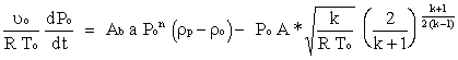
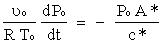
 equation 3 equation 3The rate at which combustion products flow through the nozzle throat is limited by the condition of choked flow. As described in the Nozzle Theory Web Page, the flow achieves sonic (Mach 1) velocity at the narrowest portion of the convergent-divergent nozzle (throat). Flow velocity, at this location, can never exceed the local speed of sound, and is said to be in a choked condition. This allows us to determine the rate at which the combustion products flow through the nozzle is given by equation 4: (for derivation, see Theory Appendix D )  equation 4 equation 4Note that R = R'/ M, where R' is the universal gas constant, and M is the effective molecular weight of the combustion products. Mass flow rate through the nozzle is seen to be a function of the chamber pressure (which determines the flow density), throat area, and the gas properties (which establish sonic velocity). The principle of mass conservation requires the balance between mass generation rate and the sum of the rates at which mass storage in the chamber and outflow through the nozzle:  equation 5 equation 5Substituting equations 1 & 3 into equation 5 gives:  equation 6 equation 6Propellant burn rate may be expressed in terms of the chamber pressure by the Saint Robert's law (see Propellant Burn Rate Web Page): where a and n are the burn rate coefficient and pressure exponent, respectively. Substituting equations 7 & 4 (mass flowrate through nozzle) into equation 6 leads to the following equation:  equation 8 equation 8From the ideal gas law, the density derivative in the above equation may be expressed as:  equation 9 equation 9As well, considering that chamber temperature, To, is essentially independent of chamber pressure, equation 8 may be re-written as:
 equation 10 equation 10This is a particularly useful equation, as it allows us to determine the rate of change of chamber pressure (dPo/ dt ) during the transient start-up phase of motor operation, where the chamber pressure is rapidly climbing up to the operating steady-state level. Once the steady-state phase is reached, when the outflow of combustion gases is in equilibrium with the production of gases from propellant consumption, dPo/ dt = 0, and the left-hand side of equation 10 vanishes. The steady-state chamber pressure may then be expressed as:  equation 11 equation 11
Note that the combustion product density term has been dropped, as it is small in comparison to the propellant density. 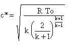 This leads to the simplified expression for steady-state chamber pressure:
 equation 12 equation 12where r is the burn rate at the chamber pressure, Po and noting that Kn = Ab/A*. It is important to note that burn rate, r, is a function of chamber pressure. As such, chamber pressure is not a direct function of Kn, rather for a given propellant, the relationship is: where C is a constant relating the propellant properties:
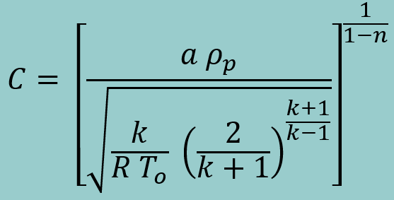 equation 12b equation 12b
The third and final phase of the pressure curve, the tail-down phase, ideally occurs immediately after the propellant grain has been completely consumed. In actuality, slivers or fragments of propellant grain remain once the bulk of the grain has been consumed. This results in a pressure tail-down that is more gradual than for the ideal case. However, it is impractical to account for this effect, and the tail-down pressure is determined on the assumption that the grain has been fully depleted.
 equation 13 equation 13This differential equation may then be solved to express tail-off chamber pressure as a function of bleeddown time for choked flow:
 equation 14 equation 14where Pbo is the chamber pressure at burn-out and t is the time from burn-out. The pressure is seen to exhibit exponential decay. An example of steady-state chamber pressure calculation, for the Kappa-DX motor, is provided in Theory Appendix E. Worked Examples |

