J/K MOTOR DESIGN AND PERFORMANCE
Ready availability of parts and simplicity of design was the driving factor for the concept of J/K motors. Unlike traditional design scenarios where components like the nozzle and the casing are custom machined to provide a given level of performance, availability of off-the-shelf items with set dimensions was the major design consideration for these motors. A few calculations suggested that a casing made from 2" PVC pipe could hold enough propellant to achieve a significant increase in total impulse over the "I" motor. From experiments performed with the "G" motor, it was estimated that the ultimate strength of 2" Schedule 40 PVC pipe was in the region of 665 psi. Thus, pressures would have to be limited to values less than 665 psi that would provide a safe margin for error.
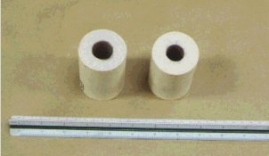
If the same techniques were to be used to build the J/K motor as was used with the smaller motors, brass tubing would be used to make the nozzle bushing. The largest brass tubing that was readily available off-the-shelf had an OD of 5/8". This would mean that a 9/16" USS flat washer could be used for the nozzle insert. This is not to say that bushings of a greater size could not be found or machined to make even larger motors, but to keep to the concept simple, the nozzle throat diameter was set at 0.625" (5/8") to match the availability of parts.
Since the PVC pipe has a limited pressure range, a grain configuration that produced a relatively flat pressure response was desirable. Multi-segmented Bates grains with an inhibited outside burn surface can be designed to give such a response. Short grain segments are also easier to cast than a single long grain and experience has been gained in casting grain segments with inhibitor sleeves. The concept of the freestanding grain was also employed to prevent cracks from developing in the grain during the burn to assure reliable operation.
Ignition is by a through-the-nozzle electric match. An ignition initiator made from a slurry mix of black powder and alcohol is painted on both the top and bottom end surfaces of the segments. A thick layer of initiator is also painted on the inside surface of the top 1 inch of the core of the top segment to help spread the flames. Richard Nakka's work with the KSB-001 and KSB-002 motors suggest that an initiator may not necessarily improve performance, but it is employed to give quick ignition of the motor which occurs almost instantaneously after the ignition of the electric match.
With these concepts and factors determined, it was a matter of using a spreadsheet model to configure a Bates grain that would theoretically produce a flat pressure response with a respectable total impulse. A motor with a "J" rating was designed, built and tested first which had the following characteristics and performance curves:
J MOTOR DESCRIPTION
| Motor weight | 63.2 oz. |
| Motor Length | 18.75 in. |
| Motor Outside Diameter (Max) | 2.281 in. (2-13/16") |
| Casing ID (Typical) | 2.04 in. |
| Propellant | KN/Sorbitol (65/35) |
| Propellant Weight | 975 grams (34.4 oz.) |
| Grain Type | Bates |
| Grain Segments | 4 |
| Grain Length | 15 in. |
| Grain OD (w/o inhibitor) | 1.97 in. |
| Core Diameter | 1.0 in. |
| Kn, Min/Max | 213/234 |
| Nozzle Throat Diameter | 0.625 in. (5/8") |
| Nozzle Throat Insert | 9/16" USS Flat Washer |
| Nozzle Expansion Ratio | 4:1 |
| |
"J" MOTOR PERFORMANCE
ESTIMATED PERFORMANCE CURVE FOR THE "J" MOTOR
Three "J" motors were tested. In all cases the motor performed flawlessly. There was no nozzle blow-by and there was no deformation of the motor casing from the heat of combustion. The motor casing was blackened on the inside surface, but there was no sign of erosion. The motor was only slightly warm to the touch immediately following the firing.
Performance was measured using a simple homemade test stand. It was the same test stand that was used to measure the thrust curves for the "G", "H", and "I" motors, but configured to handle the larger J/K motors. The test stand uses a set of calibrated springs to measure the thrust. The compression of the spring with time is recorded by an ink pen onto a strip of paper on rotating drum. A Bar-B-Que rotisserie motor drives the drum. The test stand is Science Fairish, but effective.
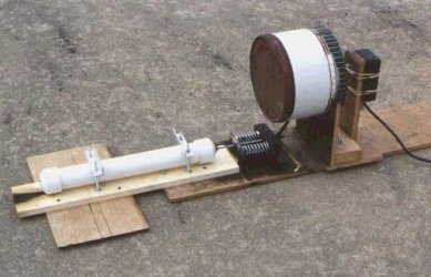
TEST STAND WITH "J/K" MOTOR
In the photo above, each of the 2 springs have a compression strength 75 lbs./in. for total compression strength of 150 lbs./in. The rocket motor casing rides on 2 rollers to eliminate sliding friction.
Following is the thrust curve and performance summary for the "J" motor:
"J" MOTOR THRUST CURVE
J MOTOR PERFORMANCE
| Motor Rating | J601 |
| Total Impulse | 1202 Ns |
| Peak Thrust | 188 lbs. |
| Average Thrust | 135 lbs. |
| Burn Time | 2.0 s |
| Specific Impulse | 126 s |
| Average Cf (Isp x g / c*) | 1.35 |
| Est. Peak Operating Pressure | 447 psi |
"J" MOTOR PERFORMANCE SUMMARY
With the success of the "J" motor a motor using the same casing and nozzle was designed that would give 20% more impulse and have a "K" classification. To achieve this level of performance, the grain was lengthened by 1-1/4", divided into 5 segments, and the core diameter was decreased to 0.75".
By decreasing the core diameter the Ac/At ratio decreased from 2.52 for the "J" motor to 1.44 for the "K" motor. This reduced value for the Ac/At ratio was of some concern since the thrust curve of the "I" motor, which had an Ac/At ratio of 1.65 shows signs of erosive burning or core stripping. If one looks at the thrust curve for the "I" motor, there is no solid line showing the leading edge. It is believed that thrust build up of the "I" motor was so rapid that it jerked the test stand and caused the recording pen to skip. Also, upon careful examination of the "I" motor's thrust curve there is a skip mark on the paper on the leading edge of the curve above the mid portion of the curve. This is also suggesting early-elevated thrust levels in the burn, which may have been caused by erosive burning. The apparent erosive burning was noticed, but ignored in the evaluation of the "I" motor. Because 2" PVC pipe has limited pressure-handling capabilities, steps were taken to reduce the risk of erosive burning. The core diameter of the bottom segment of the core where flow rates are fastest was increased from 0.75" to 0.875" (7/8"), which produced an Ac/At ratio of 1.96. This number is close to the Ac/At ratio of 2.25 for the KSB-002 motor, which shows no signs of erosive burning.
"K" MOTOR CORE SIZE COMPARISON
The spreadsheet model was modified to account for the different core sizes and produced the following design and estimated performance characteristics:
K MOTOR DESCRIPTION
| Motor weight | 73.4 oz. |
| |
| Motor Length | 20.0 in. |
| Outside Diameter (Max) | 2.281 in. (2-13/16") |
| Casing ID (Typical) | 2.04 in. |
| Propellant | KN/Sorbitol (65/35) |
| Propellant Weight | 1209 grams (42.6 oz.) |
| Grain Type | Bates |
| Grain Segments | 5 |
| Grain Length | 16.25 in. |
| Grain OD (w/o inhibitor) | 1.97 in. |
| Core Diameter | 4 x 0. 75 in. |
| 1 x 0.875 in. |
| Kn (Max/Min) | 213/237 |
| Nozzle Throat Diameter | 0.625 in. (5/8") |
| Nozzle Throat Insert | 9/16" USS Washer |
| Nozzle Expansion ratio | 4:1 |
"K" MOTOR PERFORMANCE
ESTIMATED PERFORMANCE CURVE FOR THE "K" MOTOR
The hook at the end of the thrust curve is the depletion of the propellant in the bottom segment before depletion of the propellant in the upper segments.
The "K" motor produced excellent test results. The casing and nozzle showed no signs of blow-by, casing deformation or erosion and the divergence section of the concrete nozzle had negligible erosion despite the long burn time. Following is the thrust curve and performance summary for the "K" motor:
"K" MOTOR THRUST CURVE
Note that there is no evidence of erosive burning and there is some suggestion of the "hook" on the trailing edge of the curve as predicted by the model.
K MOTOR Performance
| Motor Rating | K589 |
| Total Impulse | 1443 Ns |
| Peak Thrust | 213 lbs. |
| Average Thrust | 132 lbs. |
| Burn Time | 2.45 s |
| Specific Impulse | 121 s |
| Average Cf (Isp x g / c*) | 1.30 |
| Est. Peak Operating Pressure | 533 psi |
"K" MOTOR PERFORMANCE SUMMARY
The performance of the J/K motors is similar to Richard Nakka's KSB motors. That is, they exhibit a more progressive burn than predicted. To make this comparison more obvious, the aspect of the axes of the "K" motor thrust curve has been altered in the following graph.
COMPARATIVE VIEW OF THE "K" MOTOR THRUST CURVE
The peak thrust in both the "J" and "K" motors is also greater than expected. This would suggest that the burn rate is faster than predicted or the Kn is increasing faster than predicted. One condition that could account for both or either of these conditions is erosive burning. However, if erosive burning were occurring, it would be expected that the overall burn time would be shorter. The fact is the overall burn time for both motors is approximately 25% longer than predicted. It is also unlikely that Kn is increasing as a result of cracks or a breakdown in the inhibitor sleeve since there is no discontinuities in the thrust curve that would suggest a sudden increase in the burn surface.
Surprisingly, the specific impulse for the J/K motors is almost identical to the KSB motors at between 121 sec. and 126 sec. It was expected that the PVC motors would be less efficient because of the lower operating pressures and the small expansion ratio of the nozzle. Maybe this is an indication that the idiosyncrasies of Sorbitol propellant are a greater factor on performance than motor construction.
Dextrose has not been tried in these motors and it is recommended that dextrose NOT be used in the same grain configuration as for Sorbitol. Calculations indicate operating pressures begin to approach the ultimate strength of the PVC pipe if dextrose is substituted for Sorbitol. However, calculations also suggest that a properly configured propellant grain using dextrose can be designed whose total impulse and operating pressures are similar to the results achieved with Sorbitol. Sucrose is not recommended at all!

