The PVC rocket motors may be broken down into 4 main sections: (a) the motor casing, (b) nozzle, (c) propellant grain, and (d) top end closure. The following paragraphs explain the design concept for each section of the motor.
A. Motor Casing
The motor casings are made from Schedule 40 PVC water pipe. Pipe sizes or ratings are expressed in terms of inside dimension (ID) of the pipe.
| G Motor | H & I Motor | |
| Pipe Size/Rating | 1" Schedule 40 | 1-1/4" Schedule 40 |
The actual ID of PVC pipe may vary from its rating. For example, the 1-1/4" pipe used for these motors has an actual ID of 1.36".
Since PVC pipe is going to be required to withstand the heat and pressure associated with propellant combustion, it would be helpful to know the ultimate strength or bursting pressure of the pipe. To estimate what this pressure might be, a "G" motor was built with a single segment, 10" propellant grain. The long grain would assure that there was enough pressure build up to cause the motor casing to fail. The thrust of the motor was measured to the point of the casing failure. From the thrust data the pressure at the moment of failure could be computed.
Failure occurred when the motor was producing 76 pounds of thrust. The same spreadsheet program used to produce the predicted thrust curves for the "G", "H", and "I" motors was used to replicate pressures and thrusts for this motor. For this 1" PVC motor to be producing 76 pounds of thrust, the pressure would have to be 1330 psi at the time of failure.
This data can be extended to estimate the ultimate strength of 1-1/4" PVC pipe. The ultimate strength of tubing for any given wall thickness is the inverse to its ID. That is, the greater the ID of the pipe or tubing for a set wall thickness, the weaker its ultimate strength. Therefore, it can be estimated that 1-1/4" PVC pipe has an ultimate strength of 978 psi under the operating conditions of these motors.
Knowing the ultimate strength of the motor casing can provide some estimate of the safety margin.
| G Motor | H Motor | I Motor | |
| Safety Margin | 2.48 | 1.72 | 1.50 |
It would be nice if the margin for the "H" and "I" motors were better than shown here, but there has never been a failure of any of these motors when the design provided in this article has been followed faithfully. It is recognized that each individual has his or her own way of doing things and it may be sometimes necessary to make substitutions of materials. It is therefore recommended to perform static tests on your motor before launching in a rocket. It is better to have a failure on the ground than to destroy a rocket in the air. Once you achieve a reliable design, it is important to be consistent in your design and assembly processes. Even slight variations from a proven design can be catastrophic.
It should also be noted that when PVC pipe fails under pressure, it shatters into many sharp edge pieces. This makes these motors potentially dangerous. Also, when the casing ruptured the stresses extended into the end caps and the end caps shattered equally as much as the casing.
B. Nozzle
The nozzle is a convergent-divergent deLaval nozzle cast inside the motor casing and retained in position by a PVC end cap in which a hole is drilled through the end to allow the flow of the exhaust gasses. The convergent section of the nozzle forms a 60o angle with the axis of the nozzle and the divergence section a 15o angle with the axis. The exit port expansion ratio ranges from 4:1 for the "G" and "H" motors and 3:1 for the "I" motor. Steel washers form the throat of the nozzle to eliminate erosion in this region of the nozzle.
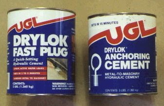
The casting material used for these nozzles is concrete. The concrete can be purchased as FAST PLUG or ANCHORING CEMENT made by United Gilsonite Laboratories (UGL) under the brand name of DRYLOK. These are fast setting hydraulic concretes. Depending on ambient temperature, FAST PLUG sets in about 5 minutes and the ANCHORING CEMENT takes about 10 to 15 minutes to set. There are other manufacturers of these types of concrete that would perform just as well. DURHAM'S ROCK HARD WATER PUTTY is another water mix castable material that could be used.
None of these casting materials can withstand the erosive action of the exhaust gasses. To stabilize nozzle erosion, steel washers are cast into the concrete to maintain the throat diameter during the propellant burn. The following table gives the size of the washers used to form the throat of the nozzle for each of the motors. Washers are rated for the bolt size with which they are to be used. However, there can be a number of different actual ID and OD dimensions for washers for the same bolt size depending on the standard. The washers used for these nozzles are US Standard (USS) Flat Steel Washers, which have an ID that is 1/16" (0.0625 in.) larger than its rating. Most of the "hardware store" variety of flat steel washers is the USS type. If other standards are followed, choose washers with the actual ID listed below.
| G Motor | H Motor | I Motor | |
| USS Flat Steel Washer - Bolt Size | 3/16" | 1/4" | 3/8" |
| Actual Center Hole ID | 0.250 in. (1/4") | 0.312 in. (5/16") | 0.437 in. (7/16") |
Another problem with concrete is that it does not adhere well to PVC. This can cause a tiny separation between the concrete and PVC pipe that can develop into a blow-by of the nozzle by the exhaust gasses. To improve the concrete's adhesion to the PVC, the inside of the PVC pipe in the region of the nozzle is painted with low luster or flat latex/acrylic house paint. The paint is allowed to dry thoroughly before the concrete is cast into the casing. The paint acts as a primer, which adheres to the PVC and provides a surface to which the concrete can adhere to form a tight seal between the PVC and concrete.
C. Propellant Grain
The propellant is KN/Sorbitol (65/35) which is cast into a freestanding, hollow-cylindrical grain. A freestanding grain is one, which is cast separate from the motor casing and inserted into the motor when the motor is assembled. The grain is not bonded to the casing, which allows combustion gasses to surround the grain and apply pressure upon the grain equally from all directions. For a detailed explanation why this is important, refer to Richard Nakka's article on Case-bonding of a High-Modulus Propellant Grain
The grain configuration for the "G" and "H" motors is a hollow-cylindrical grain. The grain for the "I" motor is a multi-segment Bates grain, which is made from two "H" grains. To learn more about these grains, refer to Richard Nakka's article Rocket Motor Design Charts -- Chamber Pressure . The outside surface of the grain is inhibited so burning occurs only within the core and on the end surfaces. The inhibitor is a paper sleeve, in which the propellant is cast. The sleeve affords sufficient thermal protection to prevent the outside surface from igniting.
More propellant than what is actually needed is mixed in preparation of casting the grain. This extra propellant allows for spillage and waste. The grain is also cast long and then trimmed to length to allow for shrinkage, which adds to the waste.
The author has not used either dextrose or sucrose propellants in these motors, so performance and reliability with these propellants are not known.

D. Top End Closure
The top end closure contains a delay grain and ejection charge for ejection of a parachute after the rocket has had a chance to coast to a maximum altitude. The delay grain assembly is a piece of 1/2" PVC water pipe, which is pinched around its center to form a restriction. An epoxy based delay grain is been packed into one end of the pipe and the restriction holds and retains the delay grain. A "timing" hole is drilled into the top end of the delay grain to set the delay time. The space above the delay grain holds an ejection charge of black powder. The black powder is ignited from the bottom of the timing hole and the upper, unburned portion of the delay grain forms a plug that directs the ejection gasses forward to cause the ejection of the parachute.
A collar cut from a 1/2" PVC coupler is glued to the 1/2" pipe and this assembly is inserted through a hole drilled in the end cap. The collar acts as a catch ring to prevent the assembly from being expelled due to the pressure within the motor. High temperature RTV silicon gasket sealant is used to seal the space between the end cap and the delay grain assembly. The same delay grain assembly will fit within either a 1" end cap or a 1-1/4" end cap so it can be used with all three motors.
A washer is used to seal the delay grain assembly from the combustion chamber. The washer size depends on the size of the end cap. For the 1" end cap, a 7/16" USS Flat Steel Washer is used. For the 1-1/4" end cap a 1/2" x 1-1/2" Fender Washer is used.. The washer serves 2 functions. First, it protects and helps to seal the delay grain assembly from the direct heat and gasses of the combustion chamber. Second, as the epoxy based delay grain burns it produces a heavy ash, which tends to flake and self extinguish the delay grain. The washer prevents the flaking of the ash and keeps the delay grain burning. The whole top end closure assembly is glued onto the casing during the final assembly of the motor.
The delay grain is a mixture of potassium nitrate and 10X Confectionery Powdered Sugar. DEVCON 5-MINUTE EPOXY is mixed with the KN/sugar mixture as a binder and as a bonding agent to the 1/2" pipe. The choice of epoxy is very important. If you are unable to locate the DEVCON epoxy try other hobby grades of epoxy adhesives. Epoxies sold for fiberglass laminating and wood sealing cannot be used. The burn rate at elevated pressure of some of these epoxies is too rapid to be suitable for a delay grain.
Following is a table with the delay time to the nearest whole second from ignition to ejection for a given length of the delay grain
| Grain Length | Delay Time From Ignition |
| 1/4" | 9 seconds |
| 3/8" | 11 seconds |
| 1/2" | 13 seconds |
These times are estimates at best. Some experimentation may be required to find more precise delays for your particular motor. However, it must be realized that a rocket travels only 64 vertical feet during the last 2 seconds of flight before reaching apogee and only 16 feet during the last 1 second. Therefore, if the ejection occurs 2 second premature before apogee, the rocket would have only missed reaching its peak altitude by 64 feet.
