Structural Testing for Design
In order to design a parachute that will be strong enough to suit the task, it is necessary to know both the loading that the parachute will experience (usually the maximum), as well as the strength of the parachute materials, such as the fabric and shroud lines. As well, since the whole thing is sewn together, it is necessary to determine the strength of the various joints, such as the panel seam joints, or the attachment of the shroud line to the canopy. Since the strength of these various components and joints are not usually known, it is necessary to do some relatively simple structural tests to determine such.
Figure 1 shows some of the specimens that I prepared for testing the design of the 1-metre diameter prototype parachute. For each of these samples, the loading direction is tensile (vertical with respect to this photo).
On the left is the sample for testing the transverse strength of the seam binding. For this test, the seam binding was sewn to pieces of reinforced fabric.
 | Second from left is the sample for testing the longitudinal strength of the panel seam joints (panels are joined with seam binding). In the centre is one of the test specimens for determining the strength of the canopy fabric. The fabric sample is adhesive bonded to two halves of a metal fixture which allows the loading to be distributed evenly over the width of the fabric sample. |
Structural Proof Load Testing
After a parachute has been designed and constructed, it is desirable to confirm the parachute structural integrity by conducting a "proof load test" which involves deploying it at the design (safe deployment) speed. For my prototype parachute, that velocity is 250 km/hr (155 mph). Since it was not practical to actually test it at such a speed, I opted for a "semi" proof load test, that is, deploying the parachute at a velocity of 130 km/hr (80 mph), to check it out for any signs of weakness. This was done by rigging a setup that would eject the parachute from the rear of my (hatchback) car at that velocity. This setup is shown in Figure 2.
 | The parachute was initially housed in a tube, from which is was ejected, at the test velocity, using a stick with attached piston. The parachute tethering loop was fastened to a 2 metre long anchoring rope, which was anchored to the hatch of the car |
After conducting this test, the parachute was carefully examined for signs of damage (no damage was found).
Parachute Drag Testing
The purpose of this series of tests is to determine the drag force that the parachute develops at various velocities. This data is particularly useful, as the descent velocity of a rocket may be determined, knowing the rockets mass. Put another way, one may determine how heavy a rocket may be recovered using the particular parachute, by knowing what descent velocity is to be achieved. As well, the drag coefficient of the parachute could be determined.
To conduct this testing, my Camaro was temporarily converted into a "flying test bed", by removing the front passenger seat and installing the test rigging, as shown in Figure 3.
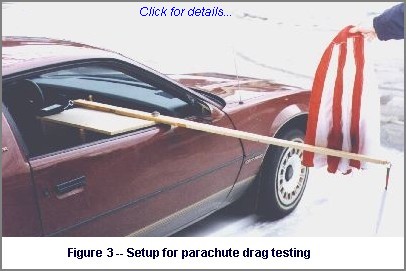 | The parachute was tethered to the end of a wooden arm, which protruded about 1.5 metres outside of the car. This arm was equipped with a pivot located 1/3 way from the inside end. In this manner, the drag force is effectively amplified by a factor of 2:1. |
Such testing was conducted at various velocities, and the results were plotted and fitted to a "best fit" curve based on the relation Fd = C * V2, where Fd = drag force, C is a constant, and V = velocity. The results are shown in Figure 4 (drag force v.s. velocity) and Figure 5 (drag coefficient v.s. velocity) for the 1-metre prototype parachute.
From the above graph (left), it can be seen that this parachute would be suitable for rockets having a weight in the range between 4 and 9 lbs, giving descent velocities of 20 ft/sec and 30 ft/sec, respectively. The average of these would probably be most suitable (6.5 lb -> 25 fps), as a descent rate of 20 fps may result in excessive drifting due to wind, and 30 fps may be considered a hard touchdown.
The Cd values were calculated based on a canopy surface area of 13.72 sq.ft., using the formula for surface area of an oblate semiellipsoid:

where a and b are the major and minor semiaxes, respectively, and e is the eccentricity, given by

Two other parachutes, both commercially manufactured (nylon), were also tested in this manner. One of these, of approximately 25 inch (64 cm) inflated diameter (71 cm circumferential, uninflated diameter), has a partly-shaped canopy that is not much different than a parasheet. The results of the drag testing for this parachute are presented in Figure 5.

From the above graph it can be seen that this parachute would be suitable for rockets having a weight in the range between 2 and 4 lbs, giving descent velocities of just over 20 ft/sec and 30 ft/sec, respectively. The average of these would probably be most suitable (3 lb -> 26 fps)
The other parachute tested was one of approximately 30 inch (76 cm.) inflated diameter (80 cm circumferential, uninflated diameter), which is of similar construction to the 25 in. parachute. This particular parachute was used on most of my C-series of rocket flights. The results of the drag testing for this parachute are presented in Figure 6.
From the above graph it can be seen that this parachute would be suitable for rockets having a weight in the range between 3 and 5 lbs, giving descent velocities of about 20 ft/sec and 30 ft/sec, respectively. The average of these would probably be most suitable (4 lb -> 26 fps)
