Introduction
This web page presents details of PRMS-4, the designation of the test flight of the Frostfire Two rocket. The Frostfire series of flights occur exclusively during the winter season (hence the name) taking advantage of an expansive frozen lake as a launch site, allowing for higher altitude flights. This allows for use of more powerful motors. In the case of Frostfire Two (as with Frostfire One), the J-class Paradigm solid rocket motor provided the propulsive power. This motor is powered by the RNX epoxy-based composite propellant.
Goals of the Frostfire Two mission are similar to those of Frostfire One, and include:
- Perform a high altitude test of the two-stage recovery technique
- Second a test flight test of the Paradigm rocket motor, fitted with a rod & tube grain configuration
- Further test the RDAS flight computer for data acquisition and recovery activation
- Perform a protracted cold-weather test of the rocket and launch support systems, including the use of chemical warmer pads for payload protection
- Determine the usefulness of an on-board radio transmitter
- Achieve a peak altitude greater than one mile (1.6 km.)
View SOAR altitude simulation program output file for Frostfire Two: soar335.txt
 | Frostfire Two is comprised of the rocket that was utilized for Flight Ze-3 of the Zephyr rocket, with certain modifications and enhancements incorporated to meet the design goals. The only significant change to the rocket configuration were the fins. The fins were enlarged to produce the desired stability margin, owing to the centre of gravity (cg) being shifted aftward by the larger, and thus heavier, motor used for this flight. Additionally, a fairing was added to the trailing end of the rocket to provide protection for the Paradigm nozzle at touchdown.
A two-stage recovery system was employed, similar to that used for flight Ze-3. The difference is that the R-DAS was additionally employed to trigger the drogue chute (this was disabled for Flight Ze-3). As such, three completely independant systems were used for drogue triggering for Frostfire Two: R-DAS, Drogue Timer, and Air-Speed Switch system. Two completely independant systems were used for main parachute deployment. The recovery system was designed to function as follows: Just prior to apogee, as the rocket slows, the A/S switch closes, firing the drogue parachute ejection charge. If the A/S fails to operate (for example, if the rocket attains significant horizontal velocity and does not slow sufficiently), R-DAS triggers drogue ejection as the rocket accelerometer sense zero magnitude acceleration. If that were to fail, the PET timer would trigger drogue ejection, following a preset delay subsequent to liftoff. The delay duration was chosen based on the SOAR simulation. Drogue parachute deployment is then followed by a fairly rapid descent to a lower altitude, at which point the main parachute ejection charge is fired, triggered by the R-DAS barometric sensor. If this system were to fail, the Main Timer would trigger the ejection charge, following a preset delay after liftoff. This delay duration was also chosen based on the SOAR simulation combined with a separate calculation of descent time based on the measured drag versus velocity characteristics of the tandem drogue chutes.
|
| External view of Frostfire Two Cutaway view of Frostfire Two |
The RDAS unit was contained within a protective glass-epoxy canister. To ensure reliable operation in the cold weather expected at launch time, the canister was encapsuled within a glass fibre insulation sleeve. Active warming of the RDAS canister was accomplished with two chemical hand-warmer packets, inserted three hours prior to launch. Prior testing had demonstrated that the packet is capable of maintaining an above-freezing temperature within the canister for over 8 hours.
The PET module which incorporates the A/S Switch, Drogue Timer and Main Timer systems, is powered by two independant 6V lithium cells for reliable cold-weather operation. To supply boosted current for the ejection charge igniters, two separate capacitor banks were hooked up, one bank in parallel to each battery. Each bank consisted of a pair of Aerogel supercapacitors, each 0.22 Farad, 2.5V wired in series (Digi-key P/N 283-2515-ND). These capacitors are very compact and feature an ultra-low ESR which allows for rapid current delivery. Testing demonstrated that the energy stored in a pair of these capacitors (1.4 Joules) was very effective in heating up a nichrome wire bridgewire.
The Radio Transmitter that was flown aboard Frostfire One was again called into service for this flight. A small modification was made, replacing the 12" tube antenna with a spiral wound antenna of identical length. The purpose of the mod was to allow the antenna to fit within the nosecone of the rocket. Additionally, it was felt that the spiral antenna is less prone to breakage on touchdown (the nosecone contacts the ground first). The purpose of the transmitter was twofold. One, to transmit the sounds within the rocket via the built-in microphone, and two, to act as a homing beacon to help locate the rocket after touchdown, should the rocket land quite distant from the launch site. To accomplish the second goal, an audio oscillator circuit was built and mounted adjacent to the transmitter. The circuit was a simple 555 based astable oscillator wired to a piezo speaker. The audio pattern was an alternating 3 hz. hi/lo signal.

Audible Oscillator circuit board.
The Paradigm motor was modified by the lengthening of the casing to allow for a slightly longer propellant grain.


Left: Paradigm rocket motor for PRMS-4
Right: Propellant grain (Rod & Tube configuration).
The grain consequently was 2 cm. longer than that used previously, with a total propellant mass of 1016 grams, up from 930 grams used for Frostfire One. As such, the motor had a constant Kn = 1021, up from 925. The main intent of increasing the Kn was to compensate for the expected cold temperature of the propellant, which had been noted in the past to reduce the burn rate noticeably. Ignition of the motor was with a pair of "Spitfire" igniters (click for photo).
A total of three parachutes were used for recovery. For the drogue system, a pair of 70x22 cm. ("1/2 metre") cross-type parachutes were employed. Average descent velocity was predicted to be 43 ft/sec (13.1 m/s) during drogue descent. The main parachute was a single "1 metre" cross-type parachute, which was recently designed & fabricated, this being its debut flight. Following main chute deployment, the anticipated descent velocity reduces to a gentle 23 ft/sec (7 m/s). Based on these decent rates, the PET Main Timer delay was set at 125 seconds from liftoff, based on a main deployment at 500 feet (150 m.). The PET Drogue Timer was set at 20 seconds following liftoff, based on an expected peak altitude of 5550 feet. The R-DAS was configured for main deployment at 760 feet (232 m.). The R-DAS backup timer feature was invoked as well, being set at 20 sec. for Drogue triggering, and at 125 seconds for main.
Both the drogue ejection charge and main ejection charge consisted of 0.80 grams of Crimson Powder.


Left: Drogue ejection charge. Note 3 pairs of wire leads, for A/S, Drogue Timer & R-DAS systems.
Right: Mounted on removable bulkhead. Also visible is tether anchor lug and quik-link.
Pre-launch weight of the rocket was 9.86 lbs (4.47 kg.); total height was 6.11 ft. (1.863 m.). The initial (minimum) stability margin was 1.53.
Download AeroLab file for Frostfire Two.
Launch Report
Sunday, Feb.15, 2004The day prior to the planned launch was spent getting the rocket configured and thoroughly checked-out for flight. As well, all supplies and equipment needed to support the launch were readied. This included charging a whole pile of batteries needed for the ignition box, FRS radios, videocameras, digital camera as well as cell phone. Lithium or NiMH were used exclusively, as regular batteries are useless in sub-zero weather. The weather reports for the launch site area were checked regularly, especially forecasted winds. Past experience had given us good confidence in the Intellicast web site for reliable wind predictions. Winds were forecast to be light in the early morning of the planned launch date, and skies were expected to clear around dawn. As such, we aimed to be out at the lakeshore prior to sunrise to begin the 5 kilometre trek onto the frozen lake. This would put us at the site just after dawn, if all went well.
To help protect the rocket from the cold and to keep both the motor and the payload from cooling down excessively, the rocket was fitted into a poly/glass fibre sleeve, conveniently made from a length of 4 inch "air duct insulation sleeve" from Home Depot. To transport the rocket and supplies, a sledge was made from an old pair of skiis, onto which was mounted a large polyethylene box. The rocket and the more delicate equipment were packed into the lightweight wooden box I had fabricated 3 years earlier for transport of my Cirrus One rocket to New Mexico. Inconveniently, the box was a bit short, so I had to cut a hole in one end for the rocket to protrude from. Otherwise, all the supplies including the fold-up tripod launcher and break-apart rails fit well into the sledge.
Monday, Feb.16, 2004
After getting up in the wee hours of the morning, the first meaningful task was to activate and install the chemical warmers into the R-DAS compartment. Following this, the compartment was sealed, and the rocket slid into the insulating sleeve, and carefully packed into the transport box. A quick look outdoors indicated the overcast sky was breaking up, as predicted, and there was no discernible wind. The outdoor thermometer read a rather crisp minus 16oC. Perhaps the most essential item for our exploit was prepared next...a large thermos of hot coffee.
Two rockets were planned to be launched this day. My Frostfire Two rocket, and Rob Furtak's completely scratch-built Skywinder-Hi rocket, which had previously flown successfully several times on a "half-grain" in his K-class KNDX powered motor. This flight was to be the first with a full propellant grain. When we arrived at the lakeshore, it was still quite dark. Using flashlights, we loaded up our sledges, bundled up for warmth, strapped on our cross-country skiis, then headed out onto the snowcovered ice field. The virgin snow was quite deep and not as firm as we'd hoped, so progress was slower than expected, and effort was greater.

Starting out on our ski trek to the launch site just prior to dawn.
The crack of dawn came about two-thirds way through our journey, and was very picturesque as it illuminated the receding clouds. Not being a "morning person" by nature, I (regretably) seldom witness a sunrise. The warmth of the sun, now shining toward us, felt good and contrasted with the sting of the subzero cold air on our faces. At least there was one thing we could be grateful for in this "sterile" environment -- no biting insects or other pests that tend to plague summertime activities.

An awesome sunrise beckoned us onward
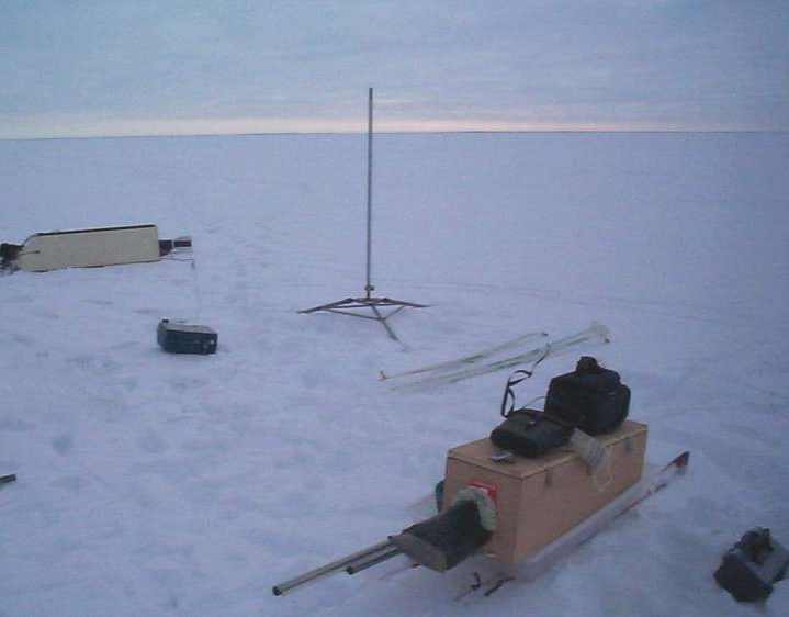
Finally, we reached our destination. We then efficiently went about our business setting up for the two much anticipated flights. We had agreed earlier that Rob's flight would be first, as his rocket used an active (electric) heating system for his payload which included a camera, the operation of which might suffer from a cold environment. While Rob got his rocket prepped for flight, I set up my EMT rail launcher. Previous launches utilized two sections of rail for a total guide length of 9 feet (2.8 m.). For this flight, I'd made up a third section providing for a total guide length of nearly 14 feet (4.3 m.) to accomodate the heavier liftoff weight (and slightly lower acceleration) of the Frostfire Two. Next, the ignition system that was being used for firing both rockets was laid out and tested. This ignition box is essentially the same unit that I built over twenty years ago. Only minor upgrades and repairs have been performed on it, such as replacing the original NiCad batteries with far superior NiMH type. I also set up the analog videocamera on a tripod approximately 20 feet away from the launch pads and covered it with a "blanket" to help protect it from the cold and wind. Fortunately, the wind was light, being only 5 km/hr.

Beginning to set up our equipment at the launch site in the dawn's early light.
(click for larger photo)
Now, Rob was nearly set to launch his rocket. The recovery system, utilizing a redundant Air-Speed Switch and Timer system (very similar to my PET system), was then armed. The igniter was connected, the ignition box armed, and we headed out to where the launch firing box was located, 500 feet away (150 m.). I manned the videocamera, while Rob had the duty of announcing countdown and pressing the firing button. On zero, the Skywinder-Hi ignited on cue, and soon after soared skyward, boosted powerfully by the short-burn, high thrust motor. Disappearing from sight, we anxiously awaited audible verification of the drogue charge. We were rewarded with the endearing"pop" sound. Next, we keenly watched for signs of the smoke charge that was designed to commence burning at apogee. It wasn't long until we spotted the white cloud of the modified KNDX smoke formulation, with the rocket descending under the guidance of the drogue parachute. The rocket descended with the smoke charge burning for nearly a minute before extinguishing. It appeared that the rocket was going to touchdown solely by drogue chute, when at the last moment, the main ejection charge was seen to fire. The main chute blossomed and the Skywinder-Hi ended its flawless flight with a soft touchdown in the snow no more that a few hundred metres away (curiously, upwind). We later estimated the peak altitude achieved was approximately 4500 feet (1375 m.), somewhat less that the targeted mile, but fully gratifying, nevertheless.
I looked upon Rob's faultless flight to be a good omen as I started to unstow and assemble my rocket, while Rob headed out to fetch his. The two forward sections of the rocket had been joined earlier in the comfort of the workshop, however, the aft section required a field joint. I cleaned and dessicated the bonding areas of the two fuselage sections with methanol, then applied the two layers of pre-cut aluminum tape strips which created the frangible element of the joint. Despite the surfaces being cold, the adhesive bonded fiercely, as expected based on prior testing. The rocket was then slid over the single length of installed launch rail and nestled neatly onto the cupped base.
By this time, Rob was back at the site, and we proceeded with the final stages of readiness. Following the steps documented on the (ever-growing) pre-launch checklist, the PET system was tested in the SAFE mode. After verifying that all was functioning nominally, connections were made to the drogue and main chute ejection charges and bridgewire continuity confirmed. After arming all three systems and replacing the hatch cover, the R-DAS thermal blanket was removed. The unit was next powered up and confirmed to be functioning. The final step of prepping the rocket for flight was the activation of the transmitter system. This performed, I installed the two remaining lengths of launch rail, which simply slid into the already-installed one. I then headed over to the tripod-mounted videocamera, turned it on, and mounted one radio receiver adjacent to it. However, that was when the first significant problem of the day occurred. The receiver, which initially picked up the pulsing signal nicely, suddenly began emitting a signal interlaced with severe static. Not wanting to delay the launch and subject the now exposed R-DAS compartment to the harsh cold unduly longer than necessary (especially since the wind had picked up slightly), I simply switched off this extra receiver. The remaining receiver unit that I had clipped to my belt was working fine. As such, I then connected the igniter leads to the rocket motor, armed the launch box, then headed over to where the firing box lay waiting.

Frostfire Two rocket & author.
As I trudged through the deep snow, I felt the familiar pseudo-calmness that seems to come once the "arm" switch has been thrown and the rocket is left on its own, duty bound in my mind, to live up to my expectations. At this point, I always know I've done all I can and whatever happens post-partum is out of my hands, my having passed the baton over to the waiting hand of fate. Arriving at the firing position, I once again unstowed the videocamera, made the necessary adjustments, then trained it on the waiting rocket. Before we could proceed with the countdown, problem number two occurred. Well, perhaps it could be labelled "part 2" of problem number one...the second radio receiver went dead. Attributing this misfortune to the effect of the cold on a device designed for use in a California climate, we quickly made the decision to abandon the transmitter objective, and proceed with the flight. The transmitter aboard the rocket was now conceded to be "dead weight" in all likelihood, but it was not a flight-critical component.
I positioned myself into a reasonably comfortable sitting posture in order to attempt to record the flight with the digital videocamera, recognizing that following a rocket through a camera lens involves panning up through nearly ninety degrees in just a matter of seconds, while simultaneously zooming in and maintaining the target within the continually narrowing field of view -- a bit challenging at the best of times, let alone with semi-numb fingers. I then informed Rob that I was "go" ! for launch.
Rob counted off the seconds to ignition... 5 - 4 - 3 - 2 - 1 - zero!
A second later, a rapidly-growing cloud of black smoke appeared at the base of the rocket signifying motor ignition. Within another second, Frostfire Two lifted off the pad and briskly accelerated skyward, leaving a dense trail of grey smoke, a trademark of the RNX propellant. The rocket initially climbed very straight and vertical, then veered slightly to the left after passing through an altitude of about 200 feet (60 m.). The rocket gained velocity at a quickening pace characterized by a continually thinning smoke trail. After approximately three seconds, motor burnout occurred and nearly immediately after, the rocket vanished from sight due to the high altitude achieved. At this point, all we could do was hold our collective breaths and wait, and listen intently for any hint of drogue deployment. Calculations had indicated it would be some 20 seconds before we'd hear audible evidence of this event, that is, if the "pop" sound could even be heard from more than a mile above us. Our diligence was rewarded after what seemed like minutes, but was likely close to the expected 20 seconds, a faint but unmistakable "pop"...!
Although we keenly continued to scan the sky, calculations suggested it'd be around a minute and a half before we could realistically expect to make visual contact, owing to the small size of the drogue chutes. I'd figured that the rocket should be visible once it had descended to an approximate altitude of 2000 feet (600 m.). I put down the videocamera, trading it for the pair of binoculars I had with me. It is only at a time such as this, that one realizes just how immensely vast the sky really is! Our waiting and searching continued, after a minute (or was it two?) of utter silence, Rob broke the tenseness with a quip "Well, Rich, I think you should go make breakfast...". I laughed, although I was also puzzled by the absence of any sign of my prized possession. Surely the rocket must be safely descending, as we'd not heard any "shrieking" sound that accompanies a rocket following a ballistic plunge to terra firma. I put down the binoculars, and regretted my earlier decision to omit the smoke charge, which had proven so effective with the Skywinder-Hi. Just then, a distinct "pop" was heard, and shortly after Rob spotted the descending rocket a few hundred feet above the frozen surface. The rocket was located, to our amazement, about 1/2 kilometre to our left -- upwind! No wonder we had not seen it earlier, we'd been looking downwind, where we would naturally expect it to have drifted during descent. I immediately grabbed the videocamera, but touchdown occurred before I was able to train the lens on the distant rocket.
I strapped on my skiis, grabbed the tow rope of the sledge, and jubilantly headed out to the recovery site. When I approached, I could see that the rocket appeared to be in perfect condition. The three fuselage sections were curiously perched upright in the snow like fenceposts. The midfuselage had come to rest directly on top of the main chute. As I got closer, I could hear both the Audible Oscillator and the R-DAS beeping. Eager to know what peak altitude had been attained, I pulled a small screwdriver out of my pocket and turned off the Oscillator which had thwarted my ability to discern the coded R-DAS beeps. Exactly five thousand, seven hundred and ninety-five feet...mission accomplished! I gathered up and stowed the rocket into the sledge, and headed back to the launch site, time to celebrate with a well-deserved mug of hot coffee.

Frostfire Two rocket at the touchdown site. In the foreground are
the two drogue chutes. The midfuselage is nestled on top of the main parachute.
Frostfire Two launch photos:
1 A fully prepped Frostfire Two sitting on launch pad.
2 Seconds away from liftoff of the Frostfire Two rocket. Skywinder-Hi, having admirably completed its mission, stands proudly by on the right.
3 Liftoff of Frostfire Two
4 View of liftoff from the close-up camera
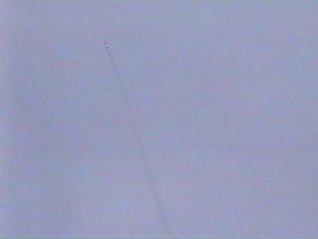
5 Rocket boldly accelerates skyward
6 After an initial vertical ascent, rocket veers slightly to the left...
7 And maintains this flight path, rapidly picking up speed and altitude
8 "Steady as she goes..."
9 Motor continues to burn perfectly
10 Nearly out of visual range
11 A pencil-thin smoke trail traces across the sky
12 Frostfire Two safely back on the surface of the frozen lake
Skywinder-Hi launch photos:
13 Rob and his venerable Skywinder-Hi rocket
14 Liftoff of the Skywinder-Hi rocket
15 Ringside view from the close-up camera
16 Exhaust blast sends chunks of snow flying
17 Drogue descent accompanied by a nice smoke trail
Post-flight Analysis
From inspection of the two video footages, the following times were excerpted:
- Ignition to liftoff -- 1.6 sec.
- Liftoff to apparent burnout -- 4.6 sec. (burnout based on sound)
- Liftoff to drogue ejection "pop" sound -- 22.5 sec.
- Liftoff to main ejection "pop" sound -- 121 sec.
- Liftoff to touchdown -- 136.5 sec..
Post-flight teardown of the rocket revealed :
- the R-DAS unit had once again functioned well, and good flight data was recorded.
- rocket, payload and parachutes were in pristine condition.
- the chemical warmers were still warm 10 hours after being activated.
- the motor suffered zero leakage.
- grain inhibitor was still fully intact with only the inside layer being somewhat charred.
- very little residue in the motor, only 28 grams representing less than 3% of the original propellant mass.

Altitude & acceleration data from R-DAS
The acceleration spikes coinciding with parachute deployment and touchdown are clearly seen. The rocket altitude and velocity during the ascent phase were next calculated by integration of the accelerometer data, yielding the following plot:
Altitude & velocity obtained from integrated accelerometer data,
compared to barometric altitude data (ascent phase only)
The inertial altitude obtained by the numerical integration of the accelerometer data suggests an apogee of 5457 feet (1664 m.). As such, the barometric and inertial altitude are in disagreement by 6%. This puzzled me at first. I'd suspected that either the R-DAS calibration was off, or that the very cold temperature at launch introduced some error into the barometric result. The latter seemed more likely, as I had wondered earlier about this possibility. I began to earnestly research this topic, consulting my reference books, the internet, and discussing this with a pilot friend. The likely reason for the deviant result soon became clear. Altimeter units such as R-DAS compute altitude from the barometric sensor data using an algorithm based on a Standard Atmosphere. This is a mathematical model which describes how properties such as air pressure and temperature change with altitude. The concept of a standardized atmosphere originally came about to satisfy the needs of safe aerial navigation (to ensure all pilots used the same reference altitudes when flying). A potential problem arises when the Standard Atmosphere is used to compute altitude. Strictly speaking, the pressure lapse rate (rate at which air pressure changes with altitude) is valid only at a location where the ground level is at Standard Temperature, which is 15oC. If ground level temperature is significantly lower (as was the case with Frostfire Two launch), the introduced error can be quite large and results in an overestimation of the altitude. How then, could I compensate for cold-weather effects? I eventually came up with two means to resolve this dilemma.
A section of the Aeronautical Information Publication (AIP) considers the issue of cold weather aerial navigation, and deals with this exact problem. Section RAC 9.17.1 stipulates a method of compensation, by use of a correction factor that is applied to an airplane's barometric altimeter reading. Specifically, it provides an equation to deal with an Off-standard Atmosphere when ambient surface temperatures are much lower than that of a Standard Atmosphere. Using this method, a chart was produced that plots geopotential altitude versus barometric altitude, at various temperatures (thanks, Michael, for the help !). The geopotential altitude is the estimated "true" altitude, the barometric is the perceived altitude. As this method was developed to ensure obstacle clearance requirements are met by low flying aircraft, it tends to be conservative in nature (tending to underestimate the geopotential altitude). Applying this to the Frostfire Two barometric data, at a ground level temperature of -15oC. and for an apparent altitude of 5800 feet, the corrected altitude becomes approximately 5200 feet, which is significantly lower, and about 5% below that reported by the accelerometer results.
The second method is far more direct. Instead of estimating a pressure lapse rate, it is certainly better to use an actual lapse rate based on measured atmospheric data! Such soundings are available on the internet, such as that provided by the University of Wyoming, Department of Atmospheric Science web site. This superb site has an archive of atmospheric soundings for hundreds of locations around the world. I retrieved the soundings taken on the morning of Feb.16, for three reporting stations, roughly forming a triangle within which the Frostfire Two launch site was located. Using this data, the atmospheric pressure at various altitudes (up to 2000 metres, or 6600 feet), as well as air temperature, was plotted. Also shown in the plot, for comparison, is the US Standard Atmosphere profile:

Sounding data for Feb.16, compared to US Std. Atm. pressure profile
The table provides the calculated (linearized) pressure function for each station, and the lapse rate ratio, given by the ratio of the slope terms (e.g. for Stn.1, lapse rate ratio = -0.1107/-0.1196 = 0.926). In the pressure functions, z is the altitude in metres, and P is pressure in hectoPascals. Note that in the graphs, the lapse rate is simply the slope of the curves. Geographically, Station 1 was closest to the launch area, while Stations 2 & 3 were quite distant, being chosen for this investigation due to the extremely low ground temperatures, in the range of -30's, which were far below the balmy standard temperature of +15C. As expected, the lapse rate ratio increasingly deviates with decreasing ground level temperature.
Using Station 1 lapse rate ratio, the adjusted barometric altitude for Frostfire Two becomes
zmax = 0.926 (5795) = 5367 feet, which is within 2% of the 5457 feet inertial altitude determined from the accelerometer data.
The sounding data also revealed very interesting air temperature profiles at the three stations. The plot below shows these profiles in comparison to the standard model of temperature lapse rate:

Sounding data for air temperature for Feb.16, compared to US Std. Atm. temperature profile
In all three cases, the ground level temperature is colder than the air above. The air temperature remains roughly constant beyond a certain altitude. Curiously, it seems that on that particular day (Feb.16), the temperature profiles were rather quirky. I also examined temperature data for Feb.17, 18 & 19th, and on these subsequent days, the temperature behaviour tended to have a more "normal" pattern. Perhaps the launch date was ill-chosen...!
Summarizing the flight results:
- Motor burn time: 3.7 seconds.
- Motor burnout altitude: 1303 feet (397 m.)
- Maximum ascent velocity: 673 feet/sec. or 459 mph. (205 m/s or 738 km/hr.)
- Max. acceleration during boost phase: 8.3 g's (approx.)
- Drogue chute deployment occurred at 17. 3 seconds, at an altitude of 5457 feet (1768 m.).
- Main chute deployment occurred at 118.7seconds after liftoff, at an altitude of approximately 740 feet (226 m.).
- Touchdown occurred at the 136.0 second mark
- Drogue descent velocity: 50.5 feet/sec., avg. (15.4 m/s.)
- Main descent velocity: 42.8 feet/sec., avg. (13.3 m/s.)
Sonic delay = 22.5 - 17.3 = 5.2 seconds (time it takes "pop" sound to reach ground).
The velocity of sound is mainly a function of temperature and humidity. At subzero temperatures, the air is essentially dry, so the only dependance is on air temperature. At -14.8oC. (the average temperature of the air through which the sound waves travelled, based on Station 1 data), acoustic velocity is 1058 ft/sec. (322.5 metres/sec). The distance, s, between the event and the microphone is
s = 1058 (5.2) = 5502 feet
which is certainly consistent with the R-DAS data. I have used this method quite often in the past for estimating peak altitude, relying on video footage to observe when the drogue chute is seen to eject (if I manage to catch this event in the video!), and then measure the time delay for the "pop" sound to reach the ground. For vertical trajectories, the calculated distance is equal to the altitude. Some error is introduced if the flight deviates from vertical, but for trajectory angles of less than, say, 10 degrees, the error is small (cosine 10 o = 0.985).
One striking anomaly is seen in the results of the descent analysis. The descent velocity under the influence of the main parachute is seen to be 42.8 ft/sec., much greater than the expected descent speed of 23 ft/sec. Clearly, the main parachute did not inflate fully. As the rocket touched down a rather distant 1/2 kilometre from the observation site, this was not noted earlier. This certainly explains one thing that had me rather puzzled when I arrived at the recovery site -- the fact that the midfuselage was nestled onto the main parachute. This scenario would not be possible if the chute had inflated, as the midfuselage would be hung beneath. As well, it explains why I did not have enough time to train the videocamera on the rocket before it landed. It appeared that by an unfortunate stroke of fate, after ejection of the main chute, the midfuselage effectively fell onto the chute before it could fully open (likely the cold played a role, making the fabric stiff), and as such, pinning it for the duration of the descent including landing, as seen in the touchdown photos. Fortunately, the deep snow provided an excellent buffer and no damage resulted from the rather hard touchdown.
The accelerometer data can additionally be used to estimate the motor performance, from the principle of force = mass x acceleration (F = m a). A "free body diagram" is illustrated below showing the forces acting on a rocket during powered flight:

where m = rocket mass, FD = aerodynamic drag, g = acceleration due to gravity, and T = motor thrust (note that all are changing with time, except g). As such, the net force acting on the rocket at any particular moment is given by:
F = T - FD - m g
Therefore, to find thrust, the mass and drag force must be estimated, at each particular moment. The mass of the rocket during the boost phase varies due to the consumption of propellant. For simplicity, this was taken as a linear function of time. The drag force was estimated using the standard equation for drag as a function of velocity, where the drag coefficient was taken as Cd=0.52 based on AeroLab analysis. The following plot of motor thrust for the Paradigm motor was derived:
Predicted versus delivered motor performance
The red curve is the predicted motor performance, based on static test data, and the blue curve is that derived from flight data (the "spikey" nature of the curve is a result of electronic noise and does not reflect the actual nature of the thrust). As expected, due to the cold temperature of the propellant prior to firing, the curve is "drawn out" with a lower thrust and longer burn. This is especially noticeable with the relatively slow thrust ramp-up, compared to the test curve. The overall impulse was consequently less, due to lower operating chamber pressure and less efficient combustion of the frigid propellant, to the tune of 5%. As such, the delivered impulse was 1041 N-s. and the delivered specific impulse was 105 seconds, down from the expected 110 seconds. The thrust profile is seen to be quite neutral, as expected owing to the neutral Kn profile of the Rod & Tube grain configuration.
One final oddity of the flight of Frostfire Two is next addressed -- the fact that the rocket landed, apparently, upwind. If we had not heard the "pop" sound of the main chute deployment, we may never have found the rocket. Undoubtedly, our search efforts would have focused on the range downwind of the launchpad. As such, it was important to resolve this paradox for the benefit of future flights. As luck would have it, the answer was found during routine examination of the video footage taken by the tripod-mounted camera. As expected, immediately following launch, the smoke cloud drifted off to the right, downwind. However, I noticed that when I fast-forwarded the tape, the low lying clouds moved away to the left ! Clearly, the surface winds were blowing in a direction more-or-less opposite to the winds aloft, explaining why the rocket landed where it did, guided by the above-surface winds. This may also explain why the rocket veered suddenly as it climbed through the approximate 200 foot altitude mark, possibly encountering a wind shear at the boundary. Can it be so that surface winds may blow in an opposite direction to winds aloft? The sounding data for one of the nearby stations is shown below for the launch date and the following day:

Sounding data for winds aloft
It is seen that the wind direction changed dramatically with increasing altitude. Over the height of about 2000 metres, the direction changed by 117 degrees on the 16th, and by 150 degrees the following day! So it is possible, or perhaps even probable, that surface winds can be misleading in judging where a rocket will land. Admittedly, I've not before encountered this sort of phenomenon....perhaps such is more common in very cold weather.
Conclusion
Frostfire Two was overall a great success, accomplishing five of the six goals. The peak altitude achieved was greater than one mile targeted, with a safe recovery of the entire rocket. The dual deployment system worked perfectly, and was only marred by the failure of the main parachute to fully inflate. The cold-weather challenge was met head on, with only minor impediments such as the failure of the radio transceivers. All key systems (including participants!) were not adversely affected to any great degree by the cold environment. The chemical warmers combined with the themal insulation blankets clearly were a success, keeping the fairweather R-DAS content and functioning. The Paradigm motor once again performed very well. Increasing the Kn for this flight was a wise decision, since the cold, as expected, slowed the burn rate markedly. An even higher Kn for winter flights can clearly be tolerated, as demonstrated by the stretched-out motor thrust curve.When the launch temperature for a particular flight is significantly lower (or above, for that matter) the Standard Temperature of 15oC (59oF.), error is introduced into the barometric altitude for any altimeter unit that uses a Standard Atmosphere calibration. Greater confidence should then be placed in the inertial altitude. As such, it would seem to be a good idea to regularly calibrate the accelerometer system (which is easily done), especially considering the shock loading that such units often see during a flight (100 g. is not uncommon during chute deployment or during touchdown). Barometric altitude can be corrected by using either the actual pressure lapse rate obtained from soundings, or by use of a cold-weather correction chart.
One important lesson learned was the essential need for a visual aid for such high altitude flights. The smoke charge that was employed for the Skywinder-Hi was very effective, and likely would have been of great benefit if such had been employed for the Frostfire Two. Other visual aids are currently being investigated, such as a flashing strobe light or a reflective streamer, or preferably a combination of these.
Lastly, it was nearly a lesson learned the hard way. That is, the important need to know the direction of the winds-aloft for high altitude rocket flights. Two possibilities come to mind with regard to methods of determining the wind direction and how it may change with increasing altitude. A small helium filled balloon, released prior to launch should accomplish this task quite well. Secondly, a small single-use rocket fitted with a small parachute that is launched beforehand. Both methods will be investigated and experiments will be conducted prior to the next Frostfire launch.
View the launch video
Note: if you are unable to play this WMV video file, e-mail me and I'll provide a link to an MPEG version.
